содержание .. 320 321 322 323 ..
Nissan Murano Z51. Manual - part 322
WHEEL SENSOR
BRC-111
< REMOVAL AND INSTALLATION >
[VDC/TCS/ABS]
C
D
E
G
H
I
J
K
L
M
A
B
BRC
N
O
P
• When installing wheel sensor, be sure to press rubber grommets in until they lock at locations shown above
in the figure. When installed, harness must not be twisted.
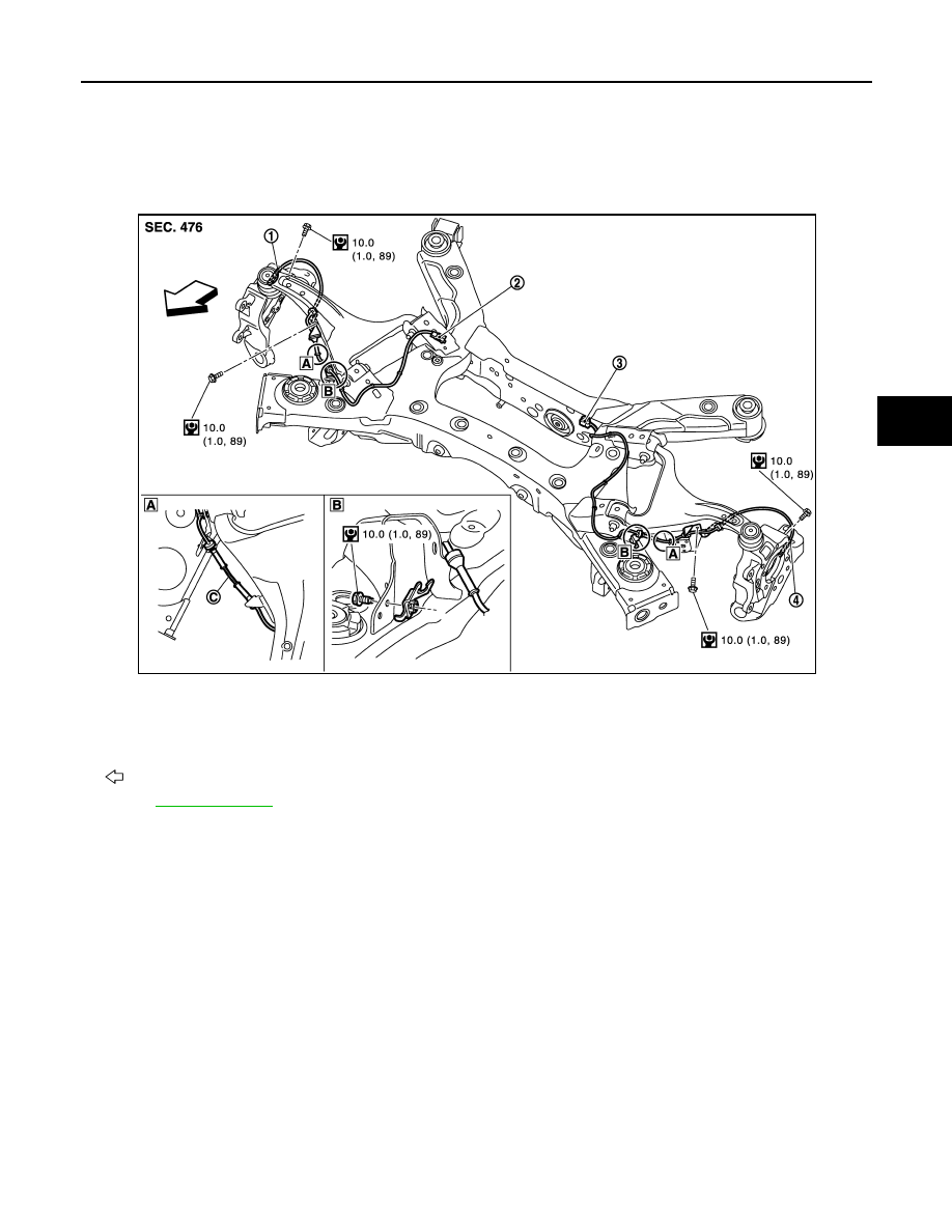
REAR WHEEL SENSOR
REAR WHEEL SENSOR : Exploded View
INFOID:0000000005517418
REAR WHEEL SENSOR : Removal and Installation
INFOID:0000000005517419
REMOVAL
Be careful with the following when removing sensor.
CAUTION:
• Never twist sensor harness as much as possible, when removing it. Pull sensors out without pulling
sensor harness.
• Be careful to avoid damaging sensor edges or rotor teeth. Remove wheel sensor first before remov-
ing front or rear wheel hub. This is to avoid damage to sensor wiring and loss of sensor function.
INSTALLATION
Be careful with the following when installing wheel sensor. Tighten installation bolts to the specified torques.
• When installing, make sure there is no foreign material such as iron chips on and in the mounting hole of the
wheel sensor. Make sure no foreign material has been caught in the sensor rotor. Remove any foreign mate-
rial and clean the mount.
• When installing wheel sensor, be sure to press rubber grommets in until they lock at locations shown above
in the figure. When installed, harness must not be twisted.
1.
Rear RH wheel sensor
2.
Rear RH wheel sensor connector
3.
Rear LH wheel sensor connector
4.
Rear LH wheel sensor
B.
AWD models only
C.
White line (slant line)
: Vehicle front
Refer to
JSFIA0191GB