Nissan Murano Z51. Manual - part 288


  Главная      Nissan     Nissan Murano Z51 (2010 year) - Service Manual


поиск по сайту            


содержание   ..  286  287  288  289   ..


Nissan Murano Z51. Manual - part 288


BRAKE PIPING

BR-23

< REMOVAL AND INSTALLATION >

C

D

E

G

H

I

J

K

L

M

A

B

BR

N

O

P

FRONT : Hydraulic Piping

INFOID:0000000005516212

FRONT : Removal and Installation

INFOID:0000000005516213

REMOVAL

CAUTION:

Never spill or splash brake fluid on painted surfaces. Brake fluid may seriously damage paint. Wipe it
off immediately and wash with water if it gets on a painted surface.

1.

Remove tires with power tool.

2.

Drain brake fluid. Refer to 

BR-12, "Draining"

.

3.

Loosen the flare nut with a flare nut wrench and separate the brake tube from the hose.

CAUTION:

• Never scratch the flare nut and the brake tube.
• Never bend sharply, twist or strongly pull out the brake hoses and tubes.
• Cover open end of brake tubes and hoses when disconnecting to prevent entrance of dirt.

4.

Remove the union bolt and copper washers, and remove the brake hose from the brake caliper assembly.

5.

Remove the lock plate and remove the brake hose.

INSTALLATION

CAUTION:

Never spill or splash brake fluid on painted surfaces. Brake fluid may seriously damage paint. Wipe it
off immediately and wash with water if it gets on a painted surface.

1.

Assemble the union bolt and the copper washers to the brake hose.

CAUTION:

Never reuse the copper washer.
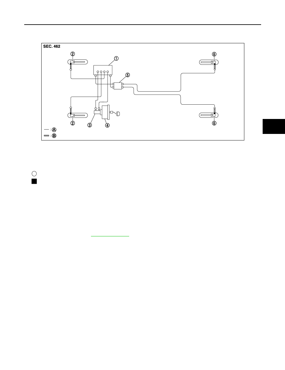
1.

ABS actuator and electric unit (con-
trol unit)

2.

Front disc brake

3.

Master cylinder assembly

4.

Brake booster

5.

Connector

6.

Rear disc brake

A.

Brake tube

B.

Brake hose

: Flare nut

: Union bolt

JPFIA0456ZZ

BR-24

< REMOVAL AND INSTALLATION >

BRAKE PIPING

2.

Align the brake hose pin to the projection (A) of the brake caliper
assembly and tighten the union bolt (1) to the specified torque.

3.

Install the brake tube to the brake hose, temporarily tighten the
flare nut by hand until it does not rotate further, and fix the brake
hose to the bracket with the lock plate.

CAUTION:

Check that all brake hoses and tubes are not twisted and
bent.

4.

Tighten the flare nut to the specified torque with a crowfoot and
torque wrench.

CAUTION:

Never scratch the flare nut and the brake tube.

5.

Refill with new brake fluid and perform the air bleeding. Refer to 

BR-13, "Bleeding Brake System"

.

CAUTION:

Never reuse drained brake fluid.

FRONT : Inspection

INFOID:0000000005516214

INSPECTION AFTER INSTALLATION

1.

Check the brake hoses and tubes for the following: no scratches; no twist and deformation; no interfer-
ence with other components when steering the steering wheel; no looseness at connections.

2.

Depress the brake pedal with a force of 785 N (80 kg, 176 lb) and hold down the pedal for approximately
5 seconds with the engine running. Check for any fluid leakage.

CAUTION:

Retighten the applicable connection to the specified torque and repair any abnormal (damaged,
worn or deformed) part if any brake fluid leakage is present.

REAR

REAR : Exploded View

INFOID:0000000005516215

JPFIA0099ZZ

JPFIA0450GB

BRAKE PIPING

BR-25

< REMOVAL AND INSTALLATION >

C

D

E

G

H

I

J

K

L

M

A

B

BR

N

O

P

REAR : Hydraulic Piping

INFOID:0000000005516216

REAR : Removal and Installation

INFOID:0000000005516217

REMOVAL

CAUTION:

Never spill or splash brake fluid on painted surfaces. Brake fluid may seriously damage paint. Wipe it
off immediately and wash with water if it gets on a painted surface.

1.

Remove tires with power tool.

2.

Drain brake fluid. Refer to 

BR-12, "Draining"

.

3.

Loosen the flare nut with a flare nut wrench and separate the brake tube from the hose.

CAUTION:

• Never scratch the flare nut and the brake tube.
• Never sharply bend, twist or strongly pull the brake hoses and tubes.
• Cover the open end of brake tubes and hoses when disconnecting to prevent entrance of dirt.

4.

Remove the union bolt and copper washers, and remove the brake hose from the brake caliper assembly.

5.

Remove the lock plate and remove the brake hose from the vehicle.

INSTALLATION

CAUTION:

Never spill or splash brake fluid on painted surfaces. Brake fluid may seriously damage paint. Wipe it
off immediately and wash with water if it gets on a painted surface.

1.

Assemble the union bolt and the copper washers to the brake hose.

CAUTION:

Never reuse copper washer.

1.

Brake tube

2.

Lock plate

3.

Brake hose

4.

Union bolt

5.

Copper washer

A.

To connector

B.

To rear brake hose

C.

To brake tube

Refer to 

GI-4, "Components"

 for symbols in the figure.

1.

ABS actuator and electric unit (con-
trol unit)

2.

Front disc brake

3.

Master cylinder assembly

4.

Brake booster

5.

Connector

6.

Rear disc brake

A.

Brake tube

B.

Brake hose

: Flare nut

: Union bolt

JPFIA0456ZZ

BR-26

< REMOVAL AND INSTALLATION >

BRAKE PIPING

2.

Install the brake hose L-pin by aligning it with the brake caliper
assembly positioning hole, and tighten the union bolt (1) to the
specified torque.

3.

Connect the hose to the brake tube, temporarily tighten the flare
nut by hand until it does not rotate further, and fix the brake hose
to the bracket with the lock plate.

CAUTION:

Check that the brake hoses and tubes are not twisted and
bent.

4.

Tighten the flare nut to the specified torque with a crowfoot and
torque wrench.

CAUTION:

Never scratch the flare nut and the brake tube.

5.

Refill with new brake fluid and perform the air bleeding. Refer to 

BR-13, "Bleeding Brake System"

.

CAUTION:

Never reuse drained brake fluid.

REAR : Inspection

INFOID:0000000005516218

INSPECTION AFTER INSTALLATION

1.

Check the brake hoses and tubes for the following: no scratches; no twist and deformation; no interfer-
ence with other components when steering the steering wheel; no looseness at connections.

2.

Depress the brake pedal with a force of 785 N (80 kg, 176 lb) and hold down the pedal for approximately
5 seconds with the engine running. Check for any fluid leakage.

CAUTION:

Retighten the applicable connection to the specified torque and repair any abnormal (damaged,
worn or deformed) part if any brake fluid leakage is present.

JPFIA0012ZZ


содержание   ..  286  287  288  289   ..