содержание .. 287 288 289 290 ..
Nissan Murano Z51. Manual - part 289
BRAKE MASTER CYLINDER
BR-27
< REMOVAL AND INSTALLATION >
C
D
E
G
H
I
J
K
L
M
A
B
BR
N
O
P
BRAKE MASTER CYLINDER
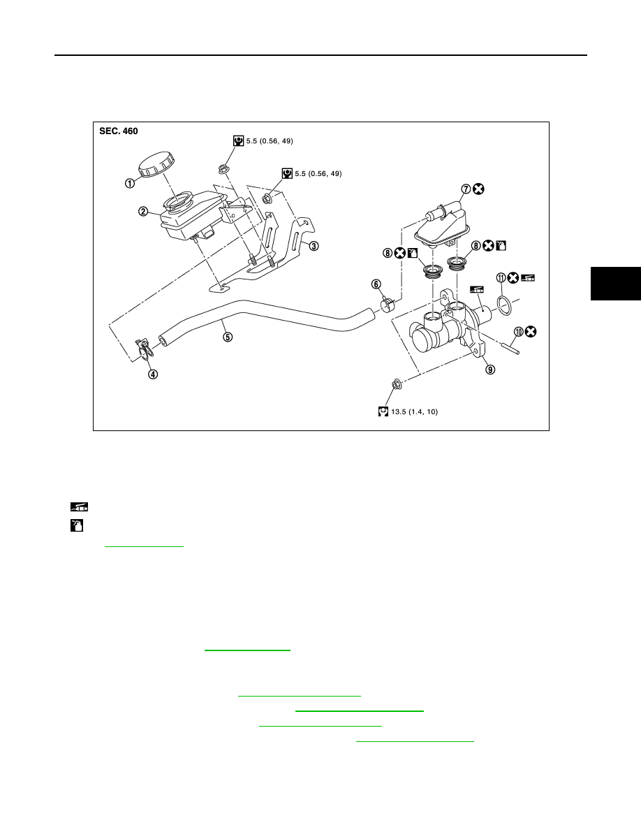
Exploded View
INFOID:0000000005516219
Removal and Installation
INFOID:0000000005516220
REMOVAL
CAUTION:
Never spill or splash brake fluid on painted surfaces. Brake fluid may seriously damage paint. Wipe it
off immediately and wash with water if it gets on a painted surface.
1.
Drain brake fluid. Refer to
2.
Separate the brake fluid level switch harness connector.
3.
Remove sub tank and hose.
4.
Remove cowl top cover. Refer to
5.
Remove front wiper drive assembly. Refer to
.
6.
Remove extension cowl top. Refer to
7.
Remove air duct assembly and air cleaner case. Refer to
.
8.
Separate the brake tubes from the master cylinder assembly with a flare nut wrench.
CAUTION:
Never scratch the flare nut and the brake tube.
9.
Remove the master cylinder assembly.
1.
Sub tank cap
2.
Sub tank
3.
Sub tank bracket
4.
Clamp
5.
Hose
6.
Clamp
7.
Reservoir tank
8.
Grommet
9.
Cylinder body
10.
Pin
11.
O-ring
: Apply PBC (Poly Butyl Cuprysil) grease or silicone-based grease.
: Apply brake fluid.
Refer to
for symbols not described on the above.
JPFIA0426GB