Nissan Murano Z51. Manual - part 286


  Главная      Nissan     Nissan Murano Z51 (2010 year) - Service Manual


поиск по сайту            


содержание   ..  284  285  286  287   ..


Nissan Murano Z51. Manual - part 286


BRAKE BOOSTER

BR-15

< PERIODIC MAINTENANCE >

C

D

E

G

H

I

J

K

L

M

A

B

BR

N

O

P

BRAKE BOOSTER

Inspection

INFOID:0000000005516203
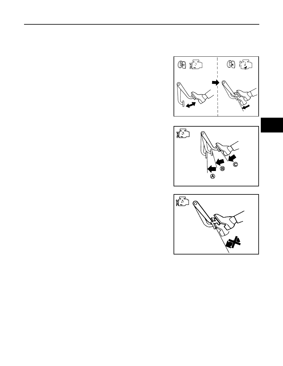
OPERATION

Depress the brake pedal several times at 5-second intervals with the
engine stopped. Start the engine with the brake pedal fully
depressed. Check that the clearance between brake pedal and dash
lower panel decreases.
NOTE:
A slight impact with a small click may be felt on the pedal when the
brake pedal is fully depressed. This is a normal phenomenon due to
the brake system operation.

AIR TIGHT

• Idle the engine for 1 minute to apply vacuum to the brake booster,

and stop the engine. Then depress the brake pedal several times
at 5-second intervals until the accumulated vacuum is released to
atmospheric pressure. Check that the clearance between brake
pedal and dash lower panel gradually increases (A 

 B 

 C) each

time the brake pedal is depressed during this operation.

• Depress the brake pedal with the engine running. Then stop the

engine while holding down the brake pedal. Check that the brake
pedal stroke does not change after holding down the brake pedal
for 30 seconds or more.
NOTE:
A slight impact with a small click may be felt on the pedal when the
brake pedal is fully depressed. This is a normal phenomenon due
to the brake system operation.

BRA0037D

JPFIA0043ZZ

JPFIA0044ZZ

BR-16

< PERIODIC MAINTENANCE >

FRONT DISC BRAKE

FRONT DISC BRAKE

BRAKE PAD

BRAKE PAD : Inspection and Adjustment

INFOID:0000000005516204

INSPECTION

Check brake pad wear thickness from an inspection hole on cylinder
body. Check using a scale if necessary. 

ADJUSTMENT

CAUTION:

• Burnish contact surfaces between pads according to the following procedure after refinishing or

replacing pads, or if a soft pedal occurs at very low mileage.

• Be careful of vehicle speed because the brake does not operate firmly/securely until pads and disc

rotor are securely fitted.

• Only perform this procedure under safe road and traffic conditions. Use extreme caution.
1.

Drive vehicle on straight, flat road.

2.

Depress brake pedal with the power to stop vehicle within 3 to 5 seconds until the vehicle stops.

3.

Drive without depressing brake for a few minutes to cool the brake.

4.

Repeat steps 1 to 3 until pad and disc rotor are securely fitted.

DISC ROTOR

DISC ROTOR : Inspection and Adjustment

INFOID:0000000005516205

INSPECTION

Appearance

Check surface of disc rotor for uneven wear, cracks, and serious damage. Replace if there are any abnormal
conditions.

Runout

1.

Fix the disc rotor to the wheel hub and bearing assembly with
wheel nuts (2 points at least).

2.

Check the wheel bearing axial end play before the inspection.
Refer to 

FAX-8, "Inspection"

 (2WD), 

FAX-35, "Inspection"

(AWD).   

3.

Inspect the runout with a dial gauge to measured at 10 mm (0.39
in) inside the disc edge.

4.

Find the installation position with a minimum runout by shifting the disc rotor-to-wheel hub and bearing
assembly installation position by one hole at a time if the runout exceeds the limit value.

5.

Refinish the disc rotor if the runout is outside the limit even after performing the above operation. [When
refinishing, use the Pro-Cut PEM On-Car brake Lathe (Tool No. 38-PFM90.5) or equivalent.]

CAUTION:

Limit

Wear thickness

: Refer to 

BR-47, "Front 

Disc Brake"

.

BRA0010D

Limit

Runout

: Refer to 

BR-47, "Front 

Disc Brake"

.

SBR019B

FRONT DISC BRAKE

BR-17

< PERIODIC MAINTENANCE >

C

D

E

G

H

I

J

K

L

M

A

B

BR

N

O

P

• Check in advance that the thickness of the disc rotor is wear thickness + 0.3 mm (0.012 in) or

more.

• If the thickness is less than wear thickness + 0.3 mm (0.012 in), replace the disc rotor.

Thickness

Check the thickness of the disc rotor using a micrometer. Replace
the disc rotor if the thickness is below the wear limit. 

ADJUSTMENT

CAUTION:

• Burnish contact surfaces between pads according to the following procedure after refinishing or

replacing pads, or if a soft pedal occurs at very low mileage.

• Be careful of vehicle speed because the brake does not operate firmly/securely until pads and disc

rotor are securely fitted.

• Only perform this procedure under safe road and traffic conditions. Use extreme caution.

1.

Drive vehicle on straight, flat road.

2.

Depress brake pedal with the power to stop vehicle within 3 to 5 seconds until the vehicle stops.

3.

Drive without depressing brake for a few minutes to cool the brake.

4.

Repeat steps 1 to 3 until pad and disc rotor are securely fitted.

Limit

Wear thickness

: Refer to 

BR-47, "Front Disc Brake"

.

Limit

Wear thickness

: Refer to 

BR-47, "Front 

Disc Brake"

.

Thickness variation

: Refer to 

BR-47, "Front 

Disc Brake"

.

SBR020B

BR-18

< PERIODIC MAINTENANCE >

REAR DISC BRAKE

REAR DISC BRAKE

BRAKE PAD

BRAKE PAD : Inspection and Adjustment

INFOID:0000000005516206

INSPECTION

Check brake pad wear thickness from an inspection hole on cylinder
body. Check using a scale if necessary. 

ADJUSTMENT

CAUTION:

• Burnish contact surfaces between pads according to the following procedure after refinishing or

replacing pads, or if a soft pedal occurs at very low mileage.

• Be careful of vehicle speed because the brake does not operate firmly/securely until pads and disc

rotor are securely fitted.

• Only perform this procedure under safe road and traffic conditions. Use extreme caution.
1.

Drive vehicle on straight, flat road.

2.

Depress brake pedal with the power to stop vehicle within 3 to 5 seconds until the vehicle stops.

3.

Drive without depressing brake for a few minutes to cool the brake.

4.

Repeat steps 1 to 3 until pad and disc rotor are securely fitted.

DISC ROTOR

DISC ROTOR : Inspection and Adjustment

INFOID:0000000005516207

INSPECTION

Appearance

Check surface of disc rotor for uneven wear, cracks, and serious damage. Replace if there are any abnormal
conditions.

Runout

1.

Fix the disc rotor to the wheel hub and bearing assembly with
wheel nuts (2 points at least).

2.

Check the wheel bearing axial end play before the inspection.
Refer to 

RAX-4, "Inspection"

 (2WD), 

RAX-11, "Inspection"

(AWD).   

3.

Inspect the runout with a dial gauge to measured at 10 mm (0.39
in) inside the disc edge.

4.

Find the installation position with a minimum runout by shifting the disc rotor-to-wheel hub and bearing
assembly installation position by one hole at a time if the runout exceeds the limit value.

5.

Refinish the disc rotor if the runout is outside the limit even after performing the above operation. [When
refinishing, use the Pro-Cut PEM On-Car brake Lathe (Tool No. 38-PFM90.5) or equivalent.]

CAUTION:

Limit

Wear thickness

: Refer to 

BR-47, "Rear 

Disc Brake"

.

BRA0010D

Limit

Runout

: Refer to 

BR-47, "Rear 

Disc Brake"

.

SBR019B


содержание   ..  284  285  286  287   ..