содержание .. 262 263 264 265 ..
Nissan Murano Z51. Manual - part 264
BCS
DIAGNOSIS SYSTEM (BCM)
BCS-23
< SYSTEM DESCRIPTION >
C
D
E
F
G
H
I
J
K
L
B
A
O
P
N
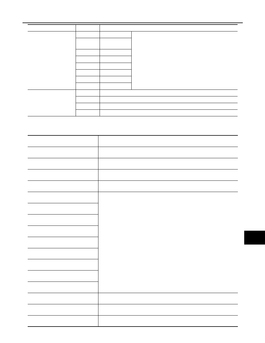
*: Factory setting
DATA MONITOR
ILL DELAY SET
MODE 1*
45 sec.
Sets delay timer function timer operation time.
(All doors closed)
MODE 2
Without the func-
tion
MODE 3
30 sec.
MODE 4
60 sec.
MODE 5
90 sec.
MODE 6
120 sec.
MODE 7
150 sec.
MODE 8
180 sec.
CUSTOM A/LIGHT SET-
TING
MODE 1*
Normal
MODE 2
More sensitive setting than normal setting (Turns ON earlier than normal operation.)
MODE 3
More sensitive setting than MODE 2 (Turns ON earlier than MODE 2.)
MODE 4
Less sensitive setting than normal setting (Turns ON later than normal operation.)
Service item
Setting item
Setting
Monitor item
[Unit]
Description
PUSH SW
[On/Off]
The switch status input from push-button ignition switch
ENGINE STATE
[Stop/Stall/Crank/Run]
The engine status received from ECM with CAN communication
VEH SPEED 1
[km/h]
The value of the vehicle speed received from combination meter with CAN commu-
nication
KEY SW-SLOT
[On/Off]
Key switch status input from key slot
TURN SIGNAL R
[On/Off]
Each switch status that BCM detects from the combination switch reading function
TURN SIGNAL L
[On/Off]
TAIL LAMP SW
[On/Off]
HI BEAM SW
[On/Off]
HEAD LAMP SW1
[On/Off]
HEAD LAMP SW2
[On/Off]
PASSING SW
[On/Off]
AUTO LIGHT SW
[On/Off]
FR FOG SW
[On/Off]
RR FOG SW
[On/Off]
NOTE:
The item is indicated, but not monitored.
DOOR SW-DR
[On/Off]
The switch status input from front door switch (driver side)
DOOR SW-AS
[On/Off]
The switch status input from front door switch (passenger side)