содержание .. 254 255 256 257 ..
Nissan Murano Z51. Manual - part 256
AV
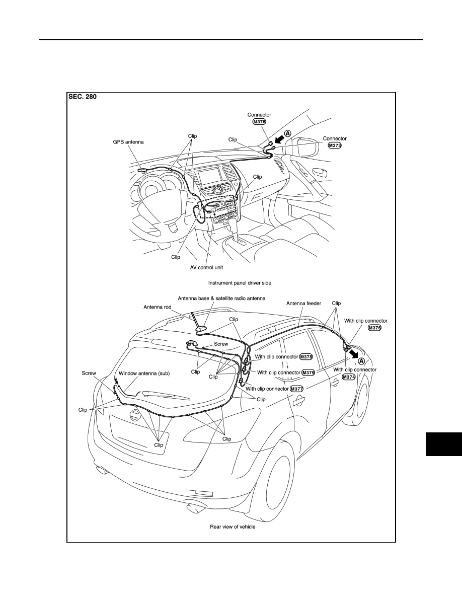
GPS ANTENNA
AV-803
< REMOVAL AND INSTALLATION >
[BOSE AUDIO WITH NAVIGATION]
C
D
E
F
G
H
I
J
K
L
M
B
A
O
P
GPS ANTENNA
Exploded View
INFOID:0000000005528851
Harness Layout
INFOID:0000000005528852
JPNIA0803GB