Nissan Murano Z51. Manual - part 197


  Главная      Nissan     Nissan Murano Z51 (2010 year) - Service Manual


поиск по сайту            


содержание   ..  195  196  197  198   ..


Nissan Murano Z51. Manual - part 197


AV

MULTI AV SYSTEM

AV-567

< SYSTEM DESCRIPTION >

[BOSE AUDIO WITH NAVIGATION]

C

D

E

F

G

H

I

J

K

L

M

B

A

O

P

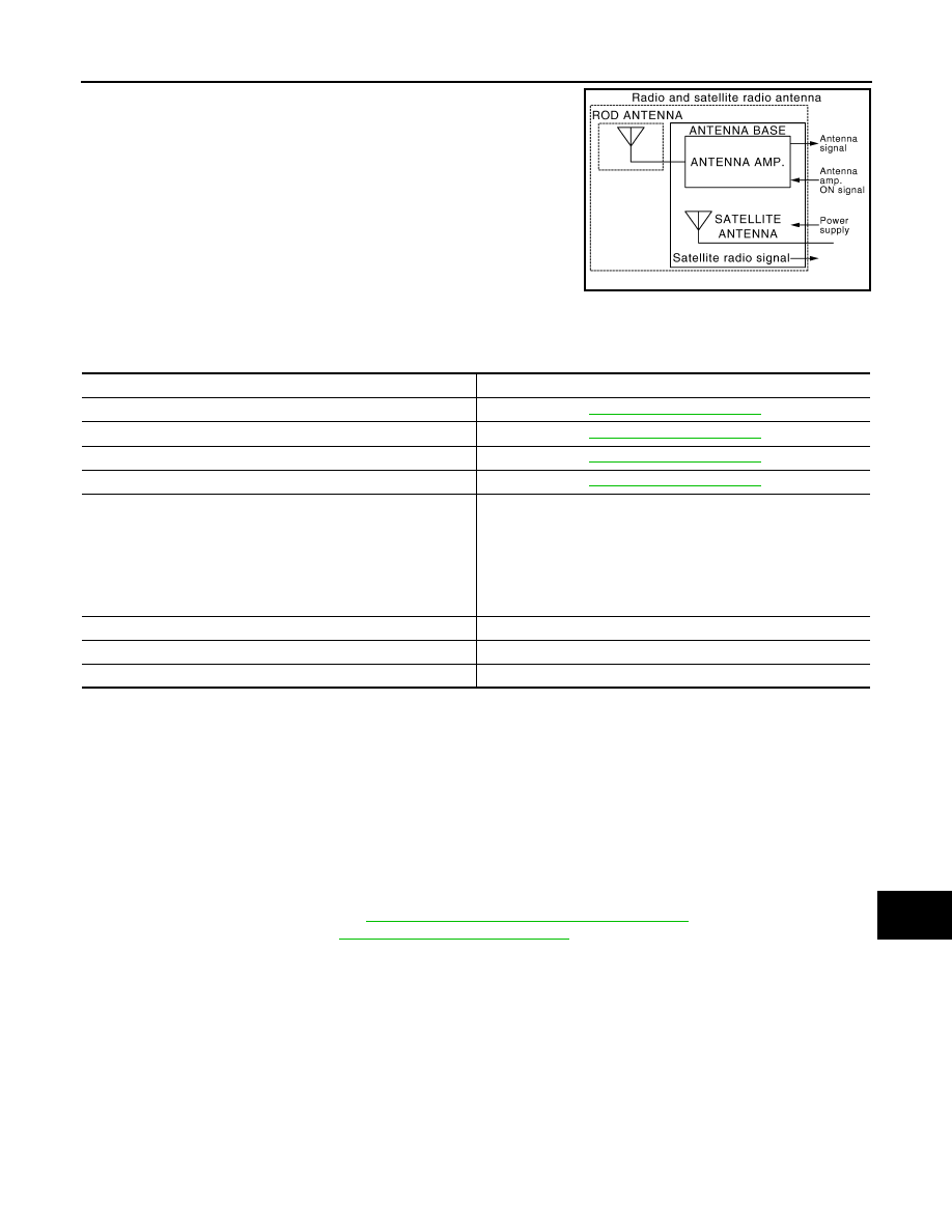
• An antenna base integrated with radio antenna amp. and satellite

radio antenna is adopted.

System Description

INFOID:0000000005528676

MULTI AV system means that the following systems are integrated.

• AV control unit function by transmitting/receiving data one by one with each unit (slave unit) that configures

them completely as a master unit by connecting between units that configure MULTI AV system with two AV
communication lines (H, L).

• Two AV communication lines (H, L) adopt a twisted pair line that is resistant to noise.
• AV control unit is connected by CAN communication, and it receives data signal from ECM, combination

meter. It computes and displays fuel economy information value with the obtained information. Transmitting/
receiving of data signal is performed by BCM. Also, it transmits the required signal of vehicle setting and
receives the response signal.

• AV control unit is connected with front display unit and serial communication, and it transmits the required

signal of display and display control and receives the response signal from front display unit.

NOTE:
AV control unit can perform CONSULT-III self-operating function and on board self-diagnosis.
• CONSULT-III self diagnosis: Refer to 

AV-601, "CONSULT-III Function (MULTI AV)"

.

• On board self diagnosis: Refer to 

AV-587, "Diagnosis Description"

.

AUXILIARY INPUT SYSTEM

• Image and sound can be output from an external device by connecting a device with auxiliary input jacks.
• Operation can be performed with multifunction switch and steering switch. Multifunction switch transmits

operation signal to AV control unit by AV communication.

• The AUX image signal is input from the auxiliary input jacks to the front display unit.

JSNIA1062GB

System name

System explanation

NAVIGATION SYSTEM

AV-572, "System Description"

AUDIO SYSTEM

AV-580, "System Description"

REAR VIEW MONITOR SYSTEM

AV-577, "System Description"

HANDS-FREE PHONE SYSTEM

AV-584, "System Description"

VEHICLE INFORMATION SYSTEM

• Status of audio, climate control system, fuel economy, mainte-

nance and navigation is displayed.

• AV control unit displays the fuel consumption status while re-

ceiving data signal through CAN communication from ECM and 
combination meter.

• AV control unit is connected to BCM via CAN communication 

transmitting/receiving for the vehicle settings function.

AUXILIARY INPUT SYSTEM

Refer to the following “AUXILIARY INPUT SYSTEM”.

VOICE RECOGNITION SYSTEM

Refer to the following “VOICE RECOGNITION SYSTEM”.

TOUCH PANEL SYSTEM

Refer to the following “TOUCH PANEL SYSTEM”.

AV-568

< SYSTEM DESCRIPTION >

[BOSE AUDIO WITH NAVIGATION]

MULTI AV SYSTEM

• The AUX sound signal is input from the auxiliary input jacks to the AV control unit. The AV control unit out-

puts the AUX sound signal to the BOSE amp. The BOSE amp. outputs the AUX sound signal to woofer and
each speaker.

VOICE RECOGNITION SYSTEM

• Each operation of multi AV system can be performed by inputting sound in to a microphone.
• Start of sound recognition system can be performed by steering switch.

TOUCH PANEL SYSTEM

Each operation of multi AV system can be performed by directly touching the appropriate display.

JSNIA1091GB

JSNIA1092GB

JSNIA0904GB

AV

MULTI AV SYSTEM

AV-569

< SYSTEM DESCRIPTION >

[BOSE AUDIO WITH NAVIGATION]

C

D

E

F

G

H

I

J

K

L

M

B

A

O

P

Component Parts Location

INFOID:0000000005528677

1.

Center speaker

2.

Front squawker LH

3.

Front door speaker LH

4.

Rear door speaker LH

5.

Rear speaker LH

6.

BOSE amp.

7.

Woofer

8.

Rear view camera

9.

Camera control unit

10. Rear speaker RH

11.

Antenna base (antenna amp. and 
satellite antenna) 

12. Rear door speaker RH

13. Front door speaker RH

14. Front squawker RH

15. Microphone

16. GPS antenna

17. Steering angle sensor

18. Steering switch

19. Auxiliary input jacks

20. iPod connector

21. iPod adapter

22. Preset switch

23. AV control unit

24. Multifunction switch

25. Front display unit

A.

Luggage floor finisher is removed 
condition

B.

Luggage side finisher lower RH is re-
moved condition

C.

Combination meter is removed condi-
tion

D.

Spiral cable part

E.

Console finisher is removed condition

JSNIA1096ZZ

AV-570

< SYSTEM DESCRIPTION >

[BOSE AUDIO WITH NAVIGATION]

MULTI AV SYSTEM

Component Description

INFOID:0000000005528678

Part name

Description

AV CONTROL UNIT

• Integrates hard disk drive (HDD) allowing map data and music data to be 

stored.

• It is the master unit of the MULTI AV system, and it is connected to each control 

unit by communication. It operates each system according to communication 
signals from the AV control unit.

• The AV control unit includes the audio, hands-free phone, voice control, navi-

gation, satellite radio, and vehicle information functions.

• It is connected to ECM, A/C auto amp. and combination meter via CAN com-

munication to obtain necessary information for the vehicle information function.

• It is connected to BCM via CAN communication transmitting/receiving for the 

vehicle settings function.

• It inputs the illumination signals that are required for the display dimming con-

trol.

• It inputs the signals for driving status recognition (vehicle speed, reverse and 

parking brake). 

• Update of map data is performed with the CONSULT-III and the applicable ca-

ble.

• It includes the TEL adapter and Bluetooth

 function.

FRONT DISPLAY UNIT

• Front display image is controlled by the serial communication from AV control 

unit.

• RGB image signal is input from AV control unit (RGB, RGB area and RGB syn-

chronizing). Auxiliary image signal is input from the auxiliary input jack. Cam-
era image signal is input from camera control unit.

• Synchronize signal (HP, VP) is output to AV control unit.
• Touch panel function can be operated for each system by touching a display 

directly.

BOSE AMP.

• Inputs power (amp. ON) and sound signal from AV control unit, and outputs 

sound signal to woofer and each speaker.

• Woofer amp. ON signal is transmitted to woofer.

WOOFER

• Composed of two woofers and a woofer amp.
• Inputs power (amp. ON) and sound signal from BOSE amp.
• Outputs low frequency sound.

FRONT DOOR SPEAKER

• Outputs sound signal from BOSE amp.
• Outputs sound (mid and low range).

REAR DOOR SPEAKER

• Outputs sound signal from BOSE amp.
• Outputs sound (mid and low range).

FRONT SQUAWKER

• Outputs sound signal from BOSE amp.
• Outputs sound (high and mid range).

REAR SPEAKER

• Outputs sound signal from BOSE amp.
• Outputs sound (high and mid range).

CENTER SPEAKER

• Outputs sound signal from BOSE amp.
• Outputs sound (high and mid range).

MULTIFUNCTION SWITCH

• Operation panel is equipped with the centralized switch where audio and aux-

iliary input operations are integrated.

• The multifunction switch is connected to the preset switch by wiring harness, 

and it transmits the operation signal to the preset switch.

PRESET SWITCH

• Operation panel is equipped with the centralized switch where audio and air 

conditioner operations are integrated.

• The preset switch is connected via AV communication, and it transmits the op-

eration signals of the preset switch and multifunction switch.

• The disk ejection operating signal is performed by wiring harness.

STEERING SWITCH

• Operations for audio, hands-free phone, audio response and navigation, etc. 

are possible.

• Steering switch signal (operation signal) is output to AV control unit.


содержание   ..  195  196  197  198   ..