содержание .. 1479 1480 1481 1482 ..
Nissan Murano Z51. Manual - part 1481
BLOWER MOTOR
VTL-95
< REMOVAL AND INSTALLATION >
[WITH 7 INCH DISPLAY]
C
D
E
F
G
H
J
K
L
M
A
B
VTL
N
O
P
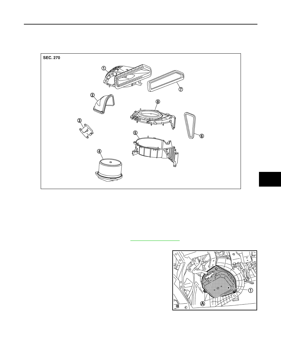
BLOWER MOTOR
Exploded View
INFOID:0000000005517202
Removal and Installation
INFOID:0000000005517203
REMOVAL
1.
Remove instrument lower panel RH. Refer to
.
2.
Disconnect the blower motor connector.
3.
Remove the mounting screws (A), and then remove the blower
motor (1).
INSTALLATION
Install in the reverse order of removal.
1.
Shutter box case
2.
Intake door
3.
Intake door motor
4.
Blower motor assembly
5.
Intake lower case
6.
Outlet seal
7.
Intake seal
8.
Intake upper case
JPIIA0455ZZ
JPIIA0568ZZ