содержание .. 1478 1479 1480 1481 ..
Nissan Murano Z51. Manual - part 1480
INTAKE SENSOR
VTL-91
< REMOVAL AND INSTALLATION >
[WITH 7 INCH DISPLAY]
C
D
E
F
G
H
J
K
L
M
A
B
VTL
N
O
P
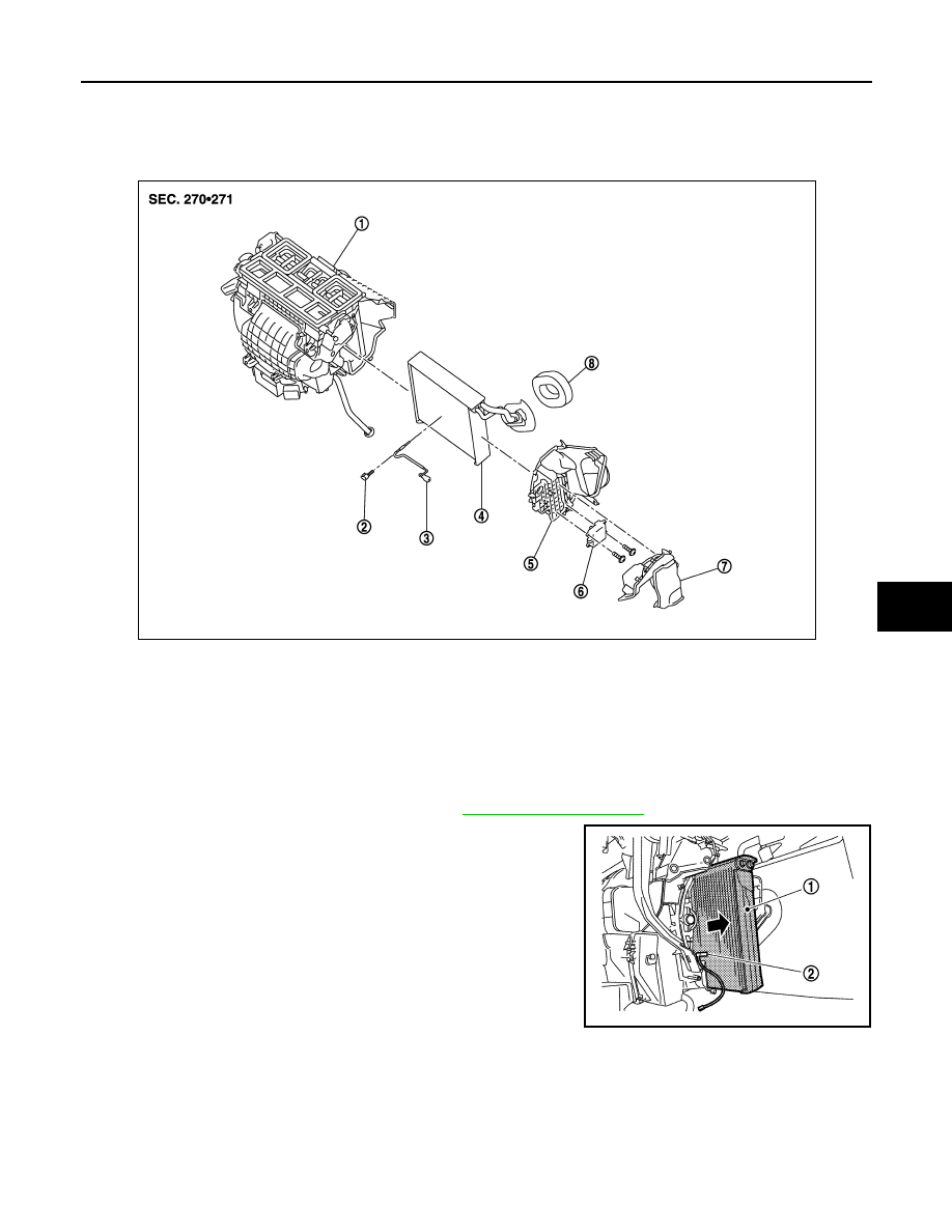
INTAKE SENSOR
Exploded View
INFOID:0000000005517198
Removal and Installation
INFOID:0000000005517199
REMOVAL
1.
Remove the evaporator pipe assembly. Refer to
.
2.
Slide the evaporator (1) toward the right side of the vehicle, and
then remove the intake sensor (2).
INSTALLATION
Note the following, and install in the reverse order of removal.
CAUTION:
• Replace the O-ring with a new one. Apply a coat of compressor oil to the O-ring prior to installation.
• Install the intake sensor in the same position as the removed intake sensor when replacing the
intake sensor.
• Do not rotate the bracket insertion part when removing and installing the intake sensor.
• Check for refrigerant leakage when charging refrigerant.
1.
Heater & cooling unit assembly
2.
Intake sensor bracket
3.
Intake sensor
4.
Evaporator assembly
5.
Evaporator cover
6.
Air mix door motor (passenger side)
7.
Foot duct (right)
8.
Cooler pipe grommet
JPIIA1303ZZ
JPIIA0907ZZ