Nissan Murano Z51. Manual - part 1212


  Главная      Nissan     Nissan Murano Z51 (2010 year) - Service Manual


поиск по сайту            


содержание   ..  1210  1211  1212  1213   ..


Nissan Murano Z51. Manual - part 1212


SE-36

< DTC/CIRCUIT DIAGNOSIS >

MOTOR SENSOR

Is the inspection result normal?

YES

>> GO TO 3.

NO

>> Repair or replace harness.

3.

CHECK MOTOR SENSOR (RH) POWER SUPPLY

1.

Connect rear seatback power return control unit connector.

2.

Check voltage between power return motor assembly (RH) harness connector and ground.

Is the inspection result normal?

YES

>> GO TO 5.

NO

>> GO TO 4.

4.

CHECK MOTOR SENSOR (RH) POWER SUPPLY CIRCUIT

1.

Disconnect rear seatback power return control unit connector.

2.

Check continuity between rear seatback power return control unit harness connector and power return
motor assembly (RH) harness connector.

3.

Check continuity between rear seatback power return control unit harness connector and ground.

Is the inspection result normal?

YES

>> Replace rear seatback power return control unit. Refer to 

SE-133, "Removal and Installation"

.

NO

>> Repair or replace harness.

5.

CHECK MOTOR SENSOR (RH) GROUND CIRCUIT 1

1.

Disconnect rear seatback power return control unit connector.

2.

Check continuity between rear seatback power return control unit harness connector power return motor
assembly harness connector.

Is the inspection result normal?

YES

>> GO TO 6.

NO

>> Repair or replace harness.

6.

CHECK MOTOR SENSOR (RH) GROUND CIRCUIT 2

1.

Connect rear seatback power return control unit connector.

2.

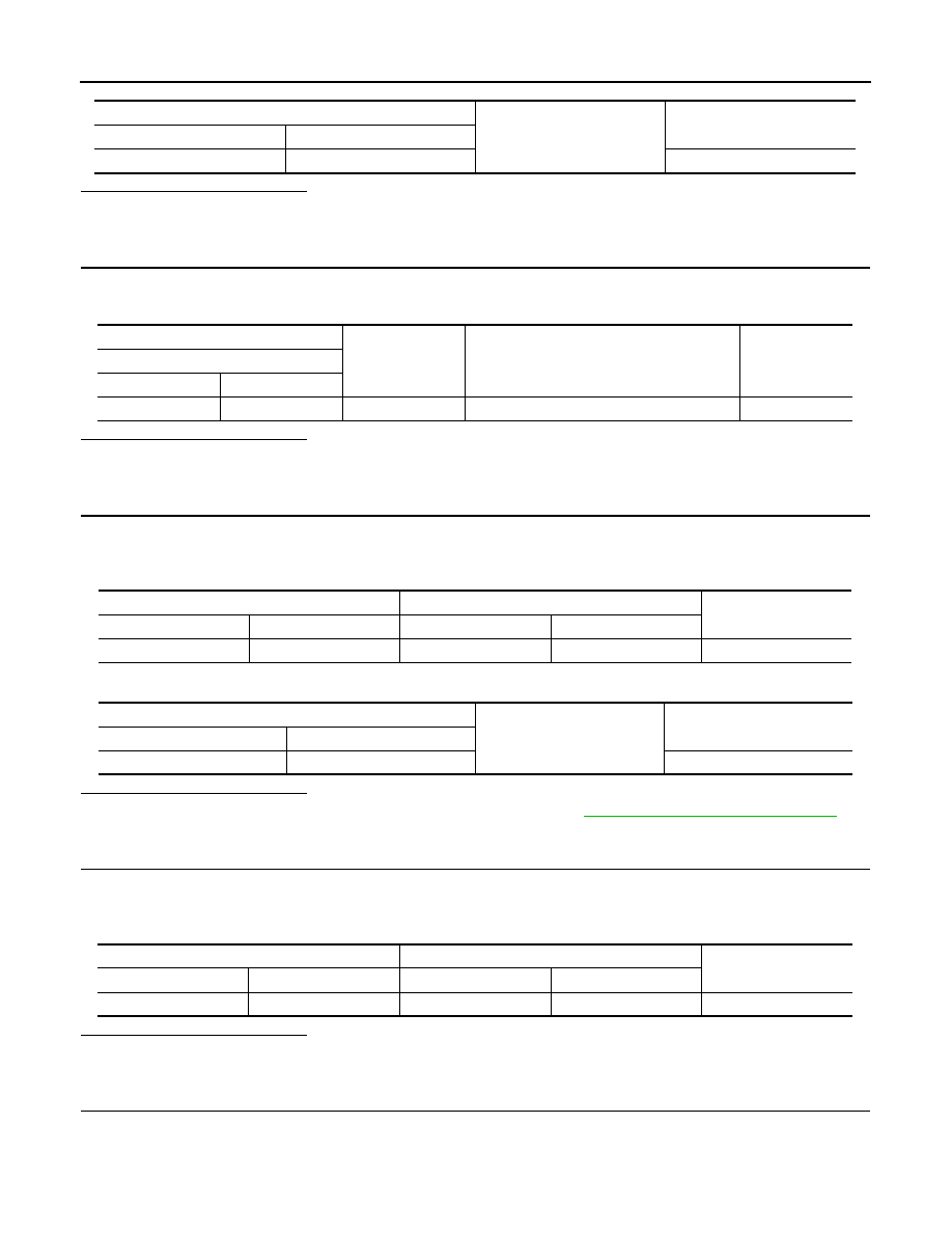
Check between rear seatback power return control unit harness connector and ground.

Rear seatback power return control unit

Ground

Continuity

Connector

Terminal

B492

2

Not existed

(+)

(–)

Condition

Voltage (V)

(Approx.)

Power return motor assembly (RH)

Connector

Terminal 

B494

6

Ground

When the power return motor is operated

Battery voltage

Rear seatback power return control unit

Power return motor assembly (RH)

Continuity

Connector

Terminal

Connector

Terminal

B492

3

B494

6

Existed

Rear seatback power return control unit

Ground

Continuity 

Connector

Terminal

B492

3

Not existed

Rear seatback power return control unit

Power return motor assembly (RH)

Continuity 

Connector

Terminal

Connector

Terminal

B492

1

B494

4

Existed

MOTOR SENSOR

SE-37

< DTC/CIRCUIT DIAGNOSIS >

C

D

E

F

G

H

I

K

L

M

A

B

SE

N

O

P

Is the inspection result normal?

YES

>> Replace motor sensor (RH) [reclining device assembly (RH)]. Refer to 

SE-120, "Exploded View"

.

NO

>> Replace rear seatback power return control unit. Refer to 

SE-133, "Removal and Installation"

.

7.

CHECK INTERMITTENT INCIDENT

Refer to 

GI-39, "Intermittent Incident"

.

>> INSPECTION END

Rear seatback power return control unit

Ground

Continuity 

Connector

Terminal

B492

9

Existed

SE-38

< DTC/CIRCUIT DIAGNOSIS >

POWER RETURN MOTOR

POWER RETURN MOTOR

LH

LH : Description

INFOID:0000000005518185

Operate the rear seatback. 

LH : Component Function Check

INFOID:0000000005518186

1.

CHECK FUNCTION

Check that the rear seatback (LH) rises when pressing and holding the power return switch (LH). 

Is the inspection result normal?

YES

>> Power return motor (LH) is OK.

NO

>> Refer to 

SE-38, "LH : Diagnosis Procedure"

.

LH : Diagnosis Procedure

INFOID:0000000005518187

1.

CHECK POWER RETURN MOTOR (LH) INPUT SIGNAL

1.

Turn ignition switch OFF.

2.

Check voltage between power return motor assembly (LH) harness connector and ground.

Is the inspection result normal?

YES

>> Replace power return motor assembly (LH) [reclining device assembly (LH)]. Refer to 

SE-120,

"Exploded View"

.

NO

>> GO TO 2.

2.

CHECK POWER RETURN MOTOR (LH) CIRCUIT

1.

Disconnect rear seatback power return control unit connector and power return motor assembly (LH) con-
nector.

2.

Check continuity between rear seatback power return control unit harness connector and power return
motor assembly (LH) harness connector. 

3.

Check continuity between rear seatback power return control unit harness connector and ground.

Is the inspection result normal?

YES

>> Replace rear seatback power return control unit. Refer to 

SE-133, "Removal and Installation"

.

(+)

(–)

Condition

Voltage (V)

(Approx.)

Power return motor assembly (LH)

Connector

Terminal

B498

1

Ground

During the power return motor (LH) return op-
eration

Battery voltage

Other than the above

0

5

During the power return motor (LH) reverse 
operation

Battery voltage

Other than the above

0

Rear seatback power return control unit 

Power return motor assembly (LH)

Continuity 

Connector

Terminal

Connector

Terminal

B492

5

B498

5

Existed

6

1

Rear seatback power return control unit 

Ground

Continuity

Connector

Terminal

B492

5

Not existed

6

POWER RETURN MOTOR

SE-39

< DTC/CIRCUIT DIAGNOSIS >

C

D

E

F

G

H

I

K

L

M

A

B

SE

N

O

P

NO

>> Repair or replace harness.

RH

RH : Description

INFOID:0000000005518188

Operate the rear seatback. 

RH : Component Function Check

INFOID:0000000005518189

1.

CHECK FUNCTION

Check that the rear seatback (RH) rises when pressing and holding the power return switch (RH). 

Is the inspection result normal?

YES

>> Power return motor (RH) is OK.

NO

>> Refer to 

SE-39, "RH : Diagnosis Procedure"

.

RH : Diagnosis Procedure

INFOID:0000000005518190

1.

CHECK POWER RETURN MOTOR (RH) INPUT SIGNAL

1.

Turn ignition switch OFF.

2.

Check voltage between power return motor assembly (RH) harness connector and ground.

Is the inspection result normal?

YES

>> Replace power return motor assembly (RH) [reclining device assembly (RH)]. Refer to 

SE-120,

"Exploded View"

.

NO

>> GO TO 2.

2.

CHECK POWER RETURN MOTOR (RH) CIRCUIT

1.

Disconnect rear seatback power return control unit connector and power return motor assembly (RH) con-
nector.

2.

Check continuity between rear seatback power return control unit harness connector and power return
motor assembly (RH) harness connector. 

3.

Check continuity between rear seatback power return control unit harness connector and ground.

Is the inspection result normal?

YES

>> Replace rear seatback power return control unit. Refer to 

SE-133, "Removal and Installation"

.

NO

>> Repair or replace harness.

(+)

(–)

Condition

Voltage (V)

(Approx.)

Power return motor assembly (RH)

Connector

Terminal

B494

1

Ground

During the power return motor (RH) return op-
eration

Battery voltage

Other than the above

0

5

During the power return motor (RH) reverse 
operation

Battery voltage

Other than the above

0

Rear seatback power return control unit 

Power return motor assembly (RH)

Continuity 

Connector

Terminal

Connector

Terminal

B492

7

B494

5

Existed

8

1

Rear seatback power return control unit 

Ground

Continuity

Connector

Terminal

B492

7

Not existed

8


содержание   ..  1210  1211  1212  1213   ..