Nissan Murano Z51. Manual - part 1037


  Главная      Nissan     Nissan Murano Z51 (2010 year) - Service Manual


поиск по сайту            


содержание   ..  1035  1036  1037  1038   ..


Nissan Murano Z51. Manual - part 1037


MWI-6

< SYSTEM DESCRIPTION >

METER SYSTEM

SYSTEM DESCRIPTION

METER SYSTEM

METER SYSTEM

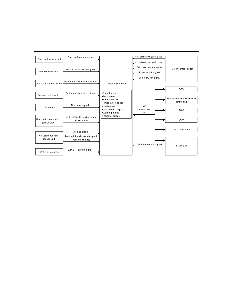
METER SYSTEM : System Diagram

INFOID:0000000005524812

METER SYSTEM : System Description

INFOID:0000000005524813

COMBINATION METER

• The combination meter receives the information required to control the operation of each gauge, indicator/

warning lamp, and information display via CAN communication from each unit, each switch, and sensor.

• The combination meter incorporates a trip computer that displays warnings and messages on the informa-

tion display according to the information received from various units.

• The combination meter incorporates a buzzer function that sounds an audible alarm with the integrated

buzzer device. Refer to 

WCS-5, "WARNING CHIME SYSTEM : System Description"

 for further details.

• The combination meter integrates the meter circuit check function and the segment check function that

checks the information display operation.

IPDM E/R

• IPDM E/R reads the ON/OFF signals of the oil pressure switch and transmits the oil pressure switch signal to

the combination meter via BCM with the CAN communication line.

• IPDM E/R is equipped with the diagnosis function. It can perform the operation check of oil pressure warning

lamp with the auto active test and the diagnosis with CONSULT-III.

METER CONTROL FUNCTION LIST

JSNIA2249GB

MWI

METER SYSTEM

MWI-7

< SYSTEM DESCRIPTION >

C

D

E

F

G

H

I

J

K

L

M

B

A

O

P

System

Description

Signal source

Meter/gauge

Speedometer

Receives vehicle speed signal and indicates vehicle speed.

ABS actuator and elec-
tric unit (control unit)

Tachometer

Receives engine speed signal and indicates engine speed.

ECM

Fuel gauge

Receives fuel level sensor signal and indicates fuel level.

Fuel level sensor unit

Engine coolant tem-
perature gauge

Receives engine coolant temperature signal and indicates coolant 
temperature.

ECM

Warning lamp/
indicator lamp

Oil pressure warning 
lamp

Receives oil pressure warning lamp signal and illuminates warning 
lamp.

IPDM E/R

Master warning

Illuminates according to warning output on information display.

Information 
display

Door open warning

Receives door switch signals and displays warning.

BCM

Parking brake re-
lease warning

Receives parking brake switch signal and vehicle speed signal and 
displays warnings.

Parking brake switch

ABS actuator and elec-
tric unit (control unit)

Low fuel warning

Receives fuel gauge signal and displays warning if fuel level de-

creases to 11 

 (2-7/8 US gal, 2-3/8 Imp gal) or less.

Fuel level sensor unit

Low washer fluid 
warning

Receives washer level switch signal and displays warning.

Washer level switch

Low outside tempera-
ture warning

Monitors ambient sensor signal and displays warning if ambient 
temperature decreases to 3

°

C (37

°

F) or less. (If enabled)

Ambient sensor

Instantaneous fuel 
consumption

Calculates instantaneous fuel consumption based on received ve-
hicle speed signals and fuel consumption monitor signal and dis-
plays it.

ECM

ABS actuator and elec-
tric unit (control unit)

Average fuel con-
sumption

Calculates average fuel consumption in a reset-to-reset interval 
based on received vehicle speed signals and fuel consumption 
monitor signal and displays it.

ECM

ABS actuator and elec-
tric unit (control unit)

Average vehicle 
speed

Calculates average vehicle speed in a reset-to-reset interval based 
on received vehicle speed signals and displays it.

ABS actuator and elec-
tric unit (control unit)

Travel time

Displays accumulated key switch ON time from reset to reset.

Travel distance

Calculates accumulated travel distance in a reset-to-reset interval 
based on received vehicle speed signals and displays it.

ABS actuator and elec-
tric unit (control unit)

Possible driving dis-
tance

Calculates possible driving distance based on received fuel con-
sumption monitor signal, vehicle speed signals and fuel level sen-
sor signal and displays it.

ABS actuator and elec-
tric unit (control unit)

ECM

Fuel level sensor unit

Ambient air tempera-
ture

Corrects ambient air temperature value based on received ambient 
sensor signals and displays it.

Ambient sensor

MWI-8

< SYSTEM DESCRIPTION >

METER SYSTEM

ARRANGEMENT OF COMBINATION METER

JPNIA0736ZZ

A.

With AWD models

B.

With Intelligent Key models

C.

For U.S.A.

D.

Except for U.S.A.

MWI

METER SYSTEM

MWI-9

< SYSTEM DESCRIPTION >

C

D

E

F

G

H

I

J

K

L

M

B

A

O

P

METER SYSTEM : Component Parts Location

INFOID:0000000005524814

JPNIA0813ZZ

1.

Fuel level sensor unit (sub)

2.

ABS actuator and electric unit (con-
trol unit)

3.

Oil pressure switch

4.

TCM

5.

Ambient sensor

6.

ECM

7.

IPDM E/R

8.

BCM

9.

Combination meter

10.

Fuel level sensor unit and fuel pump 
(main)


содержание   ..  1035  1036  1037  1038   ..