Nissan Murano Z51. Manual - part 1038


  Главная      Nissan     Nissan Murano Z51 (2010 year) - Service Manual


поиск по сайту            


содержание   ..  1036  1037  1038  1039   ..


Nissan Murano Z51. Manual - part 1038


MWI-10

< SYSTEM DESCRIPTION >

METER SYSTEM

METER SYSTEM : Component Description

INFOID:0000000005524815

SPEEDOMETER

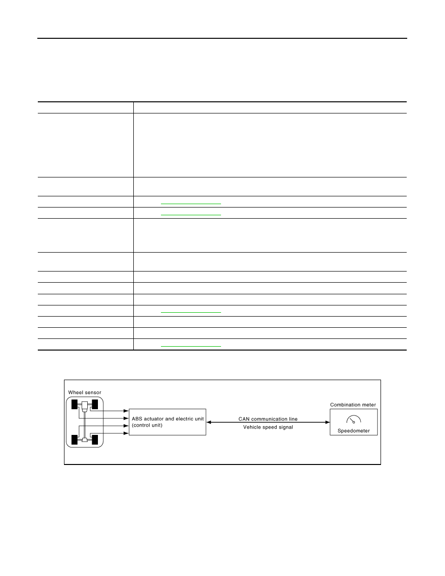
SPEEDOMETER : System Diagram

INFOID:0000000005524816

SPEEDOMETER : System Description

INFOID:0000000005524817

• The ABS actuator and electric unit (control unit) converts the rectangular wave signal provided by the wheel

sensor to a vehicle speed signal and transmits it to the combination meter via CAN communication. 

• The combination meter indicates the vehicle speed to the speedometer according to the vehicle speed sig-

nal received via CAN communication. 

A.

Lower right side of rear seat

B.

Engine room (RH)

C.

Engine front side

D.

Engine room (LH)

E.

Front bumper (left back)

F.

Engine room (LH)

G.

Engine room (LH)

H.

Behind the combination meter

I.

Lower left side of rear seat

Unit

Description

Combination meter

Controls the following with the signals received from each unit via CAN communication and the sig-
nals from switches and sensors.

• Speedometer

• Tachometer

• Engine coolant temperature gauge

• Fuel gauge

• Warning lamps

• Indicator lamps

• Information display

IPDM E/R

IPDM E/R reads the ON/OFF signals of the oil pressure switch and transmits the oil pressure switch 
signal to the combination meter via BCM with CAN communication line.

Fuel level sensor unit

Refer to 

MWI-45, "Description"

.

Oil pressure switch

Refer to 

MWI-51, "Description"

.

ECM

Transmits the following signals to the combination meter with CAN communication line.

• Engine speed signal

• Engine coolant temperature signal

• Fuel consumption monitor signal

ABS actuator and electric unit 
(control unit)

Transmits the vehicle speed signal to the combination meter with CAN communication line.

BCM

Transmits signals provided by various units to the combination meter with CAN communication line.

CVT shift selector

Transmits the O/D OFF switch signal to the combination meter.

TCM

Transmits the shift position signal to the combination meter with CAN communication line.

Meter control switch

Refer to 

MWI-48, "Description"

.

Washer level switch

Transmits the washer level signal to the combination meter.

Brake fluid level switch

Transmits the brake fluid level switch signal to the combination meter.

Parking brake switch

Refer to 

MWI-53, "Description"

.

JSNIA0289GB

MWI

METER SYSTEM

MWI-11

< SYSTEM DESCRIPTION >

C

D

E

F

G

H

I

J

K

L

M

B

A

O

P

SPEEDOMETER : Component Parts Location

INFOID:0000000005524818

JPNIA0813ZZ

1.

Fuel level sensor unit (sub)

2.

ABS actuator and electric unit (con-
trol unit)

3.

Oil pressure switch

4.

TCM

5.

Ambient sensor

6.

ECM

7.

IPDM E/R

8.

BCM

9.

Combination meter

10.

Fuel level sensor unit and fuel pump 
(main)

MWI-12

< SYSTEM DESCRIPTION >

METER SYSTEM

SPEEDOMETER : Component Description

INFOID:0000000005524819

TACHOMETER

TACHOMETER : System Diagram

INFOID:0000000005524820

TACHOMETER : System Description

INFOID:0000000005524821

• ECM converts the pulse signal provided by the crankshaft position sensor to an engine speed signal and

transmits it to the combination meter with CAN communication line.

• The combination meter indicates the engine speed to the tachometer according to the engine speed signal

received via CAN communication. 

A.

Lower right side of rear seat

B.

Engine room (RH)

C.

Engine front side

D.

Engine room (LH)

E.

Front bumper (left back)

F.

Engine room (LH)

G.

Engine room (LH)

H.

Behind the combination meter

I.

Lower left side of rear seat

Unit

Description

Combination meter

Indicates the vehicle speed to the speedometer according to the vehicle speed signal received from 
ABS actuator and electric unit (control unit) via CAN communication.

ABS actuator and electric unit 
(control unit)

Transmits the vehicle speed signal to the combination meter with CAN communication line.

JSNIA0290GB

MWI

METER SYSTEM

MWI-13

< SYSTEM DESCRIPTION >

C

D

E

F

G

H

I

J

K

L

M

B

A

O

P

TACHOMETER : Component Parts Location

INFOID:0000000005524822

JPNIA0813ZZ

1.

Fuel level sensor unit (sub)

2.

ABS actuator and electric unit (con-
trol unit)

3.

Oil pressure switch

4.

TCM

5.

Ambient sensor

6.

ECM

7.

IPDM E/R

8.

BCM

9.

Combination meter

10.

Fuel level sensor unit and fuel pump 
(main)


содержание   ..  1036  1037  1038  1039   ..