содержание .. 998 999 1000 1001 ..
Nissan Murano Z51. Manual - part 1000
OIL COOLER
LU-11
< REMOVAL AND INSTALLATION >
C
D
E
F
G
H
I
J
K
L
M
A
LU
N
P
O
REMOVAL AND INSTALLATION
OIL COOLER
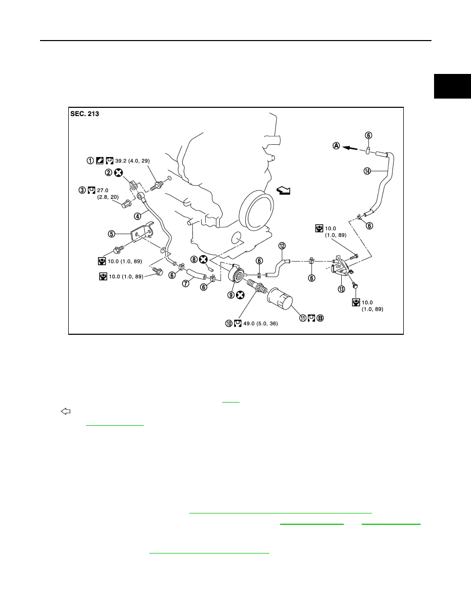
Exploded View
INFOID:0000000005515889
Removal and Installation
INFOID:0000000005515890
REMOVAL
WARNING:
Be careful not to get burn yourself, as engine oil and engine coolant may be hot.
NOTE:
When remove oil cooler only, step 2 is unnecessary.
1.
Remove splash guard (RH). Refer to
EXT-24, "FENDER PROTECTOR : Exploded View"
.
2.
Drain engine coolant from radiator and cylinder block. Refer to
NOTE:
Perform this step when removing water pipes.
3.
Remove oil filter. Refer to
LU-10, "Removal and Installation"
CAUTION:
Never spill engine oil on drive belt.
4.
Disconnect water hoses from oil cooler.
1.
Connector bolt
2.
Copper gasket
3.
Water drain plug
4.
Water pipe
5.
Bracket
6.
Clamp
7.
Water hose
8.
Relief valve
9.
Oil cooler
10.
Connector bolt
11.
Oil filter
12.
Water hose
13.
Water pipe
14.
Water hose
A.
To water connector
B.
Refer to
: Engine front
for symbols in the figure.
JPBIA1679GB