Murano Cross Cabriolet Z51 (2013 year). Manual - part 64


  Index      Manuals     Murano Cross Cabriolet Z51 (2013 year) - Service and Repair Manual


Search            copyright infringement  


Content      ..     62      63      64      65     ..


Murano Cross Cabriolet Z51 (2013 year). Manual - part 64


PCS-4

< SYSTEM DESCRIPTION >

[IPDM E/R]

COMPONENT PARTS

SYSTEM DESCRIPTION

COMPONENT PARTS

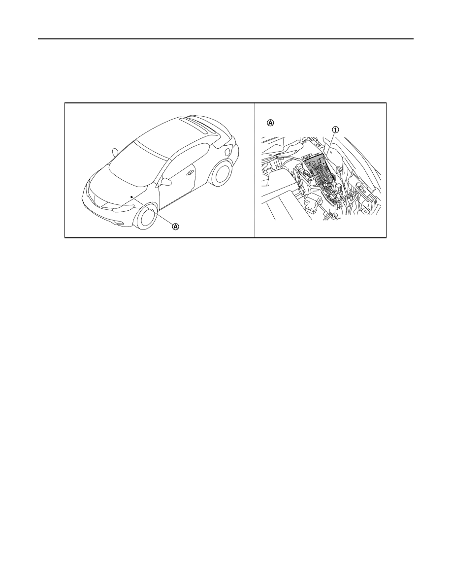
Component Parts Location

INFOID:0000000008463293

1.

IPDM E/R

A.

Engine room (LH)

JMMIA0863ZZ

Revision: 2012 October

2013 Murano CrossCabriolet

PCS

SYSTEM

PCS-5

< SYSTEM DESCRIPTION >

[IPDM E/R]

C

D

E

F

G

H

I

J

K

L

B

A

O

P

N

SYSTEM

RELAY CONTROL SYSTEM

RELAY CONTROL SYSTEM : System Diagram

INFOID:0000000008463294

RELAY CONTROL SYSTEM : System Description

INFOID:0000000008463295

IPDM E/R activates the internal control circuit to perform the relay ON-OFF control according to the input sig-
nals from various sensors and the request signals received from control units via CAN communication.
NOTE:
To prevent damage to the parts, IPDM E/R integrated relays cannot be removed.

JMMIA0623GB

Revision: 2012 October

2013 Murano CrossCabriolet

PCS-6

< SYSTEM DESCRIPTION >

[IPDM E/R]

SYSTEM

NOTE:
BCM controls the starter relay.

RELAY CONTROL SYSTEM : Fail-safe

INFOID:0000000008973102

CAN COMMUNICATION CONTROL

When CAN communication with ECM and BCM is impossible, IPDM E/R performs fail-safe control. After CAN
communication recovers normally, it also returns to normal control.

If No CAN Communication Is Available With ECM

If No CAN Communication Is Available With BCM

Control relay

Input/output

Transmit unit

Control part

Reference page

• Headlamp low relay
• Headlamp high relay

• Low beam request signal
• High beam request signal

BCM (CAN)

• Headlamp low
• Headlamp high

EXL-9

Front fog lamp relay

Front fog light request sig-
nal

BCM (CAN)

Front fog lamp

EXL-13

Tail lamp relay

Position light request signal

BCM (CAN)

• Parking  lamp
• Side marker lamp
• License plate lamp
• Tail lamp

EXL-12

Illuminations

INL-9

• Front wiper relay
• Front wiper high relay

Front wiper request signal

BCM (CAN)

Front wiper motor

WW-7

Front wiper stop position 
signal

Front wiper motor

Horn relay

• Theft warning horn re-

quest signal

• Horn reminder signal

BCM (CAN)

• Horn (low)
• Horn (high)

SEC-16

• Starter relay

NOTE

• Starter control relay

Starter control relay signal

BCM (CAN)

Starter motor

SEC-9

SEC-9

Starter relay control signal

TCM

A/C relay

A/C compressor request 
signal

ECM (CAN)

A/C compressor
(magnet clutch)

HAC-14

• Cooling fan relay-1
• Cooling fan relay-2
• Cooling fan relay-3

Cooling fan speed request 
signal

ECM (CAN)

• Cooling fan motor-1
• Cooling fan motor-2

EC-40

Ignition relay

Ignition switch ON signal

BCM (CAN)

Ignition relay 

PCS-28

Vehicle speed signal

Combination meter 
(CAN)

Push-button ignition switch 
signal

Push-button ignition 
switch

Control part

Fail-safe operation

Cooling fan

• Turns ON the cooling fan relay-2 and the cooling fan relay-3 when ignition switch is turned ON (Cooling 

fan operates at HI)

• Turns OFF the cooling fan relay-1, the cooling fan relay-2 and the cooling fan relay-3 when the ignition 

switch is turned OFF (Cooling fan does not operate)

A/C compressor

A/C relay OFF

Alternator

Outputs the power generation command signal (PWM signal) 0%

Revision: 2012 October

2013 Murano CrossCabriolet

PCS

SYSTEM

PCS-7

< SYSTEM DESCRIPTION >

[IPDM E/R]

C

D

E

F

G

H

I

J

K

L

B

A

O

P

N

IGNITION RELAY MALFUNCTION DETECTION FUNCTION

• IPDM E/R monitors the voltage at the contact circuit and excitation coil circuit of the ignition relay inside it. 
• IPDM E/R judges the ignition relay error if the voltage differs between the contact circuit and the excitation

coil circuit.

• If the ignition relay cannot turn OFF due to contact seizure, it activates the tail lamp relay for 10 minutes to

alert the user to the ignition relay malfunction when the ignition switch is turned OFF.

FRONT WIPER PROTECTION FUNCTION

IPDM E/R detects front wiper stop position by a front wiper auto stop signal.
When a front wiper stop position signal is in the conditions listed below, IPDM E/R stops power supply to wiper
after repeating a front wiper 10 seconds activation and 20 seconds stop five times.

NOTE:
This operation status can be confirmed on the IPDM E/R “Data Monitor” that displays “BLOCK” for the item
“WIP PROT” while the wiper is stopped.

STARTER MOTOR PROTECTION FUNCTION

IPDM E/R turns OFF the starter control relay to protect the starter motor when the starter control relay remains
active for 90 seconds.

POWER CONTROL SYSTEM

Control part

Fail-safe operation

Headlamp

• Turns ON the headlamp low relay when the ignition switch is turned ON
• Turns OFF the headlamp low relay when the ignition switch is turned OFF
• Headlamp high relay OFF

• Parking lamp
• License plate lamp
• Side maker lamp
• Illumination
• Tail  lamp

• Turns ON the tail lamp relay when the ignition switch is turned ON
• Turns OFF the tail lamp relay when the ignition switch is turned OFF

Front wiper motor

• The status just before activation of fail-safe control is maintained until the ignition switch is turned OFF 

while the front wiper is operating at LO or HI speed.

• The wiper is operated at LO speed until the ignition switch is turned OFF if the fail-safe control is acti-

vated while the front wiper is set in the INT/AUTO mode and the front wiper motor is operating.

• Returns automatically wiper to stop position when ignition switch is turned ON if fail-safe control is acti-

vated while front wiper motor is operated and wiper stop in the other than stop position.

Front fog lamp

Front fog lamp relay OFF

Horn

Horn relay OFF

Ignition relay

The status just before activation of fail-safe is maintained.

Starter motor

Starter control relay OFF

Voltage judgment

IPDM E/R judgment

Operation

Ignition relay contact side

Ignition relay excitation 

coil side

ON

ON

Ignition relay ON normal

OFF

OFF

Ignition relay OFF normal

ON

OFF

Ignition relay ON stuck

• Detects DTC “B2098: IGN RELAY ON”
• Turns ON the tail lamp relay for 10 minutes

OFF

ON

Ignition relay OFF stuck

Detects DTC “B2099: IGN RELAY OFF”

Ignition switch

Front wiper switch

Front wiper stop position signal

ON

OFF

The front wiper stop position signal (stop position) cannot be input for 10 seconds.

ON

The front wiper auto stop signal does not change for 10 seconds.

Revision: 2012 October

2013 Murano CrossCabriolet

PCS-8

< SYSTEM DESCRIPTION >

[IPDM E/R]

SYSTEM

POWER CONTROL SYSTEM : System Diagram

INFOID:0000000008463297

POWER CONTROL SYSTEM : System Description

INFOID:0000000008463298

ALTERNATOR CONTROL

IPDM E/R outputs power generation command signal (PWM signal) to the alternator according to the status of
the power generation command value signal received from ECM via CAN communication. Refer to 

CHG-8,

"POWER GENERATION VOLTAGE VARIABLE CONTROL SYSTEM : System Diagram"

.

SIGNAL BUFFER SYSTEM

SIGNAL BUFFER SYSTEM : System Diagram

INFOID:0000000008463299

SIGNAL BUFFER SYSTEM : System Description

INFOID:0000000008463300

• IPDM E/R reads the status of the oil pressure switch and transmits the oil pressure switch signal to BCM via

CAN communication. Refer to 

MWI-13, "WARNING LAMPS/INDICATOR LAMPS : System Diagram"

.

• IPDM E/R receives the rear window defogger control signal from BCM via CAN communication and trans-

mits it to ECM and AV control unit via CAN communication. Refer to 

DEF-5, "System Diagram"

.

POWER CONSUMPTION CONTROL SYSTEM

JPMIA0908GB

JPMIA0862GB

Revision: 2012 October

2013 Murano CrossCabriolet

PCS

SYSTEM

PCS-9

< SYSTEM DESCRIPTION >

[IPDM E/R]

C

D

E

F

G

H

I

J

K

L

B

A

O

P

N

POWER CONSUMPTION CONTROL SYSTEM : System Diagram

INFOID:0000000008463301

POWER CONSUMPTION CONTROL SYSTEM : System Description

INFOID:0000000008463302

OUTLINE

• IPDM E/R incorporates a power consumption control function that reduces the power consumption accord-

ing to the vehicle status. 

• IPDM E/R changes its status (control mode) with the sleep wake up signal received from BCM via CAN com-

munication.

Normal mode (wake-up)

- CAN communication is normally performed with other control units.
- Individual unit control by IPDM E/R is normally performed.

Low power consumption mode (sleep)

- Low power consumption control is active.
- CAN transmission is stopped.

SLEEP MODE ACTIVATION

• IPDM E/R judges that the sleep-ready conditions are fulfilled when the ignition switch is OFF and none of the

conditions below are present. Then it transmits a sleep-ready signal (ready) to BCM via CAN communica-
tion.

- Outputting signals to actuators
- Switches or relays operating
- Output requests are being received from control units via CAN communication.
• IPDM E/R stops CAN communication and enters the low power consumption mode when it receives a sleep

wake up signal (sleep) from BCM and the sleep-ready conditions are fulfilled.

WAKE-UP OPERATION

• IPDM E/R changes from the low power consumption mode to the normal mode when it receives a sleep

wake-up signal (wake up) from BCM or any of the following conditions is fulfilled. In addition, it transmits a
sleep-ready signal (not-ready) to BCM via CAN communication to report the CAN communication start.

- Ignition switch ON
- An output request is received from a control unit via CAN communication.

JMMIA0876GB

Revision: 2012 October

2013 Murano CrossCabriolet

PCS-10

< SYSTEM DESCRIPTION >

[IPDM E/R]

DIAGNOSIS SYSTEM (IPDM E/R)

DIAGNOSIS SYSTEM (IPDM E/R)

Diagnosis Description

INFOID:0000000008463303

AUTO ACTIVE TEST

Description

In auto active test mode, the IPDM E/R sends a drive signal to the following systems to check their operation.
• Oil pressure warning lamp
• Front wiper (LO, HI)
• Parking lamp
• License plate lamp
• Side maker lamp
• Tail lamp
• Front fog lamp
• Headlamp (LO, HI)
• A/C compressor (magnet clutch)
• Cooling fan

Operation Procedure

NOTE:
Never perform auto active test in the following conditions.
• CONSULT is connected
• Passenger door is open

1.

Close the hood and lift the wiper arms from the windshield. (Prevent windshield damage due to wiper
operation)
NOTE:
When auto active test is performed with hood opened, sprinkle water on windshield beforehand.

2.

Turn the ignition switch OFF.

3.

Turn the ignition switch ON, and within 20 seconds, press the front door switch (driver side) 10 times.
Then turn the ignition switch OFF.

4.

Turn the ignition switch ON within 10 seconds. After that the horn sounds once and the auto active test
starts.

5.

After a series of the following operations is repeated 3 times, auto active test is completed.

NOTE:
• When auto active test has to be cancelled halfway through test, turn the ignition switch OFF.
• When auto active test is not activated, door switch may be the cause. Check door switch. Refer to 

DLK-55,

"Component Function Check"

.

Inspection in Auto Active Test Mode

When auto active test mode is actuated, the following 6 steps are repeated 3 times.

Operation 
sequence

Inspection location

Operation

1

Oil pressure warning lamp

Blinks continuously during operation of auto active test 

2

Front wiper motor

LO for 5 seconds 

 HI for 5 seconds

3

• Parking  lamp
• License plate lamp
• Side maker lamp
• Tail lamp
• Front fog lamp

10 seconds

4

Headlamp

LO 

 HI 5 times

5

A/C compressor (magnet clutch)

ON 

 OFF 5 times

6

Cooling fan

LO for 5 seconds 

 MID for 3 seconds 

 HI for 2 seconds

Revision: 2012 October

2013 Murano CrossCabriolet

PCS

DIAGNOSIS SYSTEM (IPDM E/R)

PCS-11

< SYSTEM DESCRIPTION >

[IPDM E/R]

C

D

E

F

G

H

I

J

K

L

B

A

O

P

N

Concept of auto active test

• IPDM E/R starts the auto active test with the door switch signals transmitted by BCM via CAN communica-

tion. Therefore, the CAN communication line between IPDM E/R and BCM is considered normal if the auto
active test starts successfully.

• The auto active test facilitates troubleshooting if any systems controlled by IPDM E/R cannot be operated.

Diagnosis chart in auto active test mode

JMMIA0836GB

Symptom

Inspection contents

Possible cause

Any of the following components do not operate

• Parking lamp
• License plate lamp
• Side maker lamp
• Tail  lamp
• Front  fog  lamp
• Headlamp (HI, LO)
• Front motor wiper

Perform auto active test.
Does the applicable system 
operate?

YES

BCM signal input circuit

NO

• Lamp or motor
• Lamp or motor ground circuit
• Harness or connector between 

IPDM E/R and applicable system

• IPDM E/R

A/C compressor does not operate

Perform auto active test.
Does the magnet clutch oper-
ate?

YES

• A/C amp. signal input circuit
• CAN communication signal between 

A/C amp. and ECM

• CAN communication signal between 

ECM and IPDM E/R

NO

• Magnet clutch
• Harness or connector between 

IPDM E/R and magnet clutch

• IPDM E/R

Oil pressure warning lamp does not operate

Perform auto active test.
Does the oil pressure warning 
lamp blink?

YES

• Harness or connector between 

IPDM E/R and oil pressure switch

• Oil pressure switch
• IPDM E/R

NO

• CAN communication signal between 

IPDM E/R and BCM

• CAN communication signal between 

BCM and combination meter

• Combination meter

Revision: 2012 October

2013 Murano CrossCabriolet

PCS-12

< SYSTEM DESCRIPTION >

[IPDM E/R]

DIAGNOSIS SYSTEM (IPDM E/R)

CONSULT Function (IPDM E/R)

INFOID:0000000008463304

APPLICATION ITEM

CONSULT performs the following functions via CAN communication with IPDM E/R.

SELF DIAGNOSTIC RESULT

Refer to 

PCS-23, "DTC Index"

.

DATA MONITOR

NOTE:
The following table includes information (items) inapplicable to this vehicle. For information (items) applicable
to this vehicle, refer to CONSULT display items.

Cooling fan does not operate

Perform auto active test.
Does the cooling fan operate?

YES

• ECM signal input circuit
• CAN communication signal between 

ECM and IPDM E/R

NO

• Harness or connector between 

IPDM E/R and cooling fan motor

• Harness or connector between 

IPDM E/R and cooling fan relay

• Cooling fan motor
• Cooling fan relay
• IPDM  E/R

Symptom

Inspection contents

Possible cause

Diagnosis mode

Description

Ecu Identification

Allows confirmation of IPDM E/R part number.

Self Diagnostic Result

Displays the diagnosis results judged by IPDM E/R.

Data Monitor

Displays the real-time input/output data from IPDM E/R input/output data.

Active Test

IPDM E/R can provide a drive signal to electronic components to check their operations.

CAN Diag Support Monitor

The results of transmit/receive diagnosis of CAN communication can be read.

Monitor Item

[Unit]

MAIN SIG-

NALS

Description

MOTOR FAN REQ
[1/2/3/4]

×

Displays the value of the cooling fan speed request signal received from ECM via 
CAN communication.

AC COMP REQ
[Off/On]

×

Displays the status of the A/C compressor request signal received from ECM via 
CAN communication.

TAIL&CLR REQ
[Off/On]

×

Displays the status of the position light request signal received from BCM via CAN 
communication.

HL LO REQ
[Off/On]

×

Displays the status of the low beam request signal received from BCM via CAN 
communication.

HL HI REQ
[Off/On]

×

Displays the status of the high beam request signal received from BCM via CAN 
communication.

FR FOG REQ
[Off/On]

×

Displays the status of the front fog light request signal received from BCM via 
CAN communication.

FR WIP REQ
[Stop/1LOW/Low/Hi]

×

Displays the status of the front wiper request signal received from BCM via CAN 
communication.

WIP AUTO STOP
[STOP P/ACT P]

×

Displays the status of the front wiper auto stop signal judged by IPDM E/R.

WIP PROT
[Off/BLOCK]

×

Displays the status of the front wiper fail-safe operation judged by IPDM E/R.

IGN RLY1 -REQ
[Off/On]

Displays the status of the ignition switch ON signal received from BCM via CAN 
communication.

IGN RLY
[Off/On]

×

Displays the status of the ignition relay judged by IPDM E/R.

Revision: 2012 October

2013 Murano CrossCabriolet

PCS

DIAGNOSIS SYSTEM (IPDM E/R)

PCS-13

< SYSTEM DESCRIPTION >

[IPDM E/R]

C

D

E

F

G

H

I

J

K

L

B

A

O

P

N

ACTIVE TEST

PUSH SW
[Off/On]

Displays the status of the push-button ignition switch judged by IPDM E/R.

INTER/NP SW
[Off/On]

Displays the status of the shift position judged by IPDM E/R.

ST RLY CONT
[Off/On]

Displays the status of the starter relay status signal received from BCM via CAN 
communication.

IHBT RLY -REQ
[Off/On]

Displays the status of the starter control relay signal received from BCM via CAN 
communication.

ST/INHI RLY
[Off/ ST ON/INHI ON/UNKWN]

Displays the status of the starter relay and starter control relay judged by IPDM 
E/R.

DETENT SW
[Off/On]

Displays the status of the CVT shift selector (detention switch) judged by IPDM E/
R.

S/L RLY -REQ
[Off/On]

NOTE:
The item is indicated, but not monitored.

S/L STATE
[LOCK/UNLOCK/UNKWN]

NOTE:
The item is indicated, but not monitored.

DTRL REQ
[Off/On]

NOTE:
The item is indicated, but not monitored.

OIL P SW
[Open/Close]

Displays the status of the oil pressure switch judged by IPDM E/R.

HOOD SW
[Off/On]

NOTE:
The item is indicated, but not monitored.

HL WASHER REQ
[Off/On]

NOTE:
The item is indicated, but not monitored.

THFT HRN REQ
[Off/On]

Displays the status of the theft warning horn request signal received from BCM 
via CAN communication.

HORN CHIRP
[Off/On]

Displays the status of the horn reminder signal received from BCM via CAN com-
munication.

CRNRNG LMP REQ
[Off/On]

NOTE:
The item is indicated, but not monitored.

Monitor Item

[Unit]

MAIN SIG-

NALS

Description

Test item

Operation

Description

CORNERING LAMP

Off

NOTE:
The item is indicated, but cannot be tested.

LH

RH

HORN

On

Operates horn relay for 20 ms.

FRONT WIPER

Off

OFF

Lo

Operates the front wiper relay.

Hi

Operates the front wiper relay and front wiper high relay.

MOTOR FAN

1

OFF

2

Operates the cooling fan relay-1.

3

Operates the cooling fan relay-2.

4

Operates the cooling fan relay-2 and cooling fan relay-3.

HEAD LAMP WASHER

On

NOTE:
The item is indicated, but cannot be tested.

Revision: 2012 October

2013 Murano CrossCabriolet

PCS-14

< SYSTEM DESCRIPTION >

[IPDM E/R]

DIAGNOSIS SYSTEM (IPDM E/R)

EXTERNAL LAMPS

Off

OFF

TAIL

Operates the tail lamp relay.

Lo

Operates the headlamp low relay.

Hi

Operates the headlamp low relay and ON/OFF the headlamp high relay at 1 sec-
ond intervals.

Fog

Operates the front fog lamp relay.

Test item

Operation

Description

Revision: 2012 October

2013 Murano CrossCabriolet

PCS

IPDM E/R

PCS-15

< ECU DIAGNOSIS INFORMATION >

[IPDM E/R]

C

D

E

F

G

H

I

J

K

L

B

A

O

P

N

ECU DIAGNOSIS INFORMATION

IPDM E/R

Reference Value

INFOID:0000000008463305

VALUES ON THE DIAGNOSIS TOOL

NOTE:
The following table includes information (items) inapplicable to this vehicle. For information (items) applicable
to this vehicle, refer to CONSULT display items.

Monitor Item

Condition

Value/Status

MOTOR FAN REQ

Engine idle speed

Changes depending on engine 
coolant temperature, air conditioner 
operation status, vehicle speed, 
etc.

1/2/3/4 

AC COMP REQ

Engine running

A/C switch OFF

Off

A/C switch ON
(Compressor is operating)

On

TAIL&CLR REQ

Lighting switch OFF

Off

Lighting switch 1ST, 2ND, HI or AUTO (Light is illuminated)

On

HL LO REQ

Lighting switch OFF

Off

Lighting switch 2ND HI or AUTO (Light is illuminated)

On

HL HI REQ

Lighting switch 2ND or AUTO (light 
is illuminated)

Lighting switch other than HI and 
PASS

Off

Lighting switch HI or PASS

On

FR FOG REQ

Lighting switch 2ND or AUTO (Light 
is illuminated)

Front fog lamp switch OFF

Off

Front fog lamp switch ON

On

FR WIP REQ

Ignition switch ON

Front wiper switch OFF

Stop

Front wiper switch INT

1LOW

Front wiper switch LO

Low

Front wiper switch HI

Hi

WIP AUTO STOP

Ignition switch ON

Front wiper stop position

STOP P

Any position other than front wiper 
stop position

ACT P

WIP PROT

Ignition switch ON

Front wiper operates normally

Off

Front wiper stops at fail-safe opera-
tion

BLOCK

IGN RLY1 -REQ

Ignition switch OFF or ACC

Off

Ignition switch ON

On

IGN RLY

Ignition switch OFF or ACC

Off

Ignition switch ON

On

PUSH SW

Release the push-button ignition switch

Off

Press the push-button ignition switch

On

INTER/NP SW

Ignition switch ON

Selector lever in any position other 
than P or N

Off

Selector lever in P or N position 

On

ST RLY CONT

Ignition switch ON

Off

At engine cranking

On

Revision: 2012 October

2013 Murano CrossCabriolet

PCS-16

< ECU DIAGNOSIS INFORMATION >

[IPDM E/R]

IPDM E/R

IHBT RLY -REQ

Ignition switch ON

Off

At engine cranking

On

ST/INHI RLY

Ignition switch ON

Off

At engine cranking

INHI ON 

 ST ON

The status of starter relay or starter control relay cannot be recognized by 
the battery voltage malfunction, etc. when the starter relay is ON and the 
starter control relay is OFF

UNKWN

DETENT SW

Ignition switch ON

• Press the selector button with se-

lector lever in P position

• Selector lever in any position oth-

er than P

Off

Release the selector button with selector lever in P position

On

S/L RLY -REQ

NOTE:
The item is indicated, but not monitored.

Off

S/L STATE

NOTE:
The item is indicated, but not monitored.

UNLOCK

DTRL REQ

NOTE:
The item is indicated, but not monitored.

Off

OIL P SW

Ignition switch OFF, ACC or engine running

Open

Ignition switch ON

Close

HOOD SW

NOTE:
The item is indicated, but not monitored.

Off

HL WASHER REQ

NOTE:
The item is indicated, but not monitored.

Off

THFT HRN REQ

Not operating

Off

• Panic alarm is activated
• Theft warning alarm is activated

On

HORN CHIRP

Not operating

Off

Door locking with Intelligent Key (horn chirp mode)

On

CRNRNG LMP REQ

NOTE:
The item is indicated, but not monitored.

Off

Monitor Item

Condition

Value/Status

Revision: 2012 October

2013 Murano CrossCabriolet

PCS

IPDM E/R

PCS-17

< ECU DIAGNOSIS INFORMATION >

[IPDM E/R]

C

D

E

F

G

H

I

J

K

L

B

A

O

P

N

TERMINAL LAYOUT

PHYSICAL VALUES

JPMIA0863ZZ

Terminal No.

(Wire color)

Description

Condition

Value

(Approx.)

Signal name

Input/ 

Output

+

1

(R)

Ground

Battery power supply

Input

Ignition switch OFF

Battery voltage

2

(L)

Ground

Battery power supply

Input

Ignition switch OFF

Battery voltage

4

(LG)

Ground

Front wiper LO

Output

Ignition 
switch ON

Front wiper switch OFF

0 V

Front wiper switch LO

Battery voltage

5

(Y)

Ground

Front wiper HI

Output

Ignition 
switch ON

Front wiper switch OFF

0 V

Front wiper switch HI

Battery voltage

7

(GR)

Ground

Tail, license plate, side 
marker lamp and illumina-
tions

Output

Ignition 
switch ON

Lighting switch OFF

0 V

Lighting switch 1ST

Battery voltage

10

(BR)

Ground

ECM relay power supply

Output

Ignition switch OFF
(More than a few seconds after turning 
ignition switch OFF)

0 V

• Ignition switch ON
• Ignition switch OFF

(For a few seconds after turning igni-
tion switch OFF)

Battery voltage

12

(B)

Ground

Ground

Ignition switch ON

0 V

Revision: 2012 October

2013 Murano CrossCabriolet

PCS-18

< ECU DIAGNOSIS INFORMATION >

[IPDM E/R]

IPDM E/R

13

(SB)

Ground

Fuel pump power supply 

Output

Approximately 1 second or more after 
turning the ignition switch ON

0 V

• Approximately 1 second after turning 

the ignition switch ON

• Engine running

Battery voltage

15

(W)

Ground

Ignition relay power supply

Output

Ignition switch OFF

0 V

Ignition switch ON

Battery voltage

16

(R)

Ground

Front wiper stop position

Input

Ignition 
switch ON

Front wiper stop position

0 V

Any position other than 
front wiper stop position

Battery voltage

19

(Y)

Ground

Ignition relay power supply

Output

Ignition switch OFF

0 V

Ignition switch ON

Battery voltage

20

(L)

Ground

Ambient sensor ground

Output

Ignition switch ON

0 V

21

(O)

Ground

Ambient sensor 

Input

Ignition switch ON

0 - 4.8 V

NOTE:

Changes depending to ambient 

temperature

22

(SB)

Ground

Refrigerant pressure sen-
sor ground

Output

Engine 
running

• Warm-up condition
• Idle speed

0 V

23

(GR)

Ground

Refrigerant pressure sen-
sor

Output

Engine 
running

• Warm-up condition
• Both A/C switch and 

blower fan motor switch 
ON
(Compressor operates)

1.0 - 4.0 V

24

(G)

Ground

Refrigerant pressure sen-
sor power supply

Input

Ignition switch OFF

0 V

Ignition switch ON

5.0 V

25

(GR)

Ground

Ignition relay power supply

Output

Ignition switch OFF

0 V

Ignition switch ON

Battery voltage

26

(Y)

Ground

Ignition relay power supply

Output

Ignition switch OFF

0 V

Ignition switch ON

Battery voltage

27

(W)

Ground

Ignition relay monitor

Input

Ignition switch OFF or ACC

Battery voltage

Ignition switch ON

0 V

28

(SB)

Ground

Push-button ignition 
switch

Input

Press the push-button ignition switch

0 V

Release the push-button ignition switch

Battery voltage

30

(BR)

Ground

Starter relay control 

Input

Ignition 
switch ON

Selector lever in any posi-
tion other than P or N

0 V

Selector lever P or N

Battery voltage

34

(O)

Ground

Cooling fan relay-3 control

Input

Cooling fan stopped

Battery voltage

Cooling fan at HI operation

0 V

35

(Y)

Ground

Cooling fan relay-1 power 
supply

Input

Cooling fan stopped

Battery voltage

Cooling fan at LO operation

6.0 V

36

(G)

Ground

Battery power supply

Input

Ignition switch OFF

Battery voltage

38

(W)

Ground

Cooling fan relay-1 power 
supply

Output

Cooling fan not operating

0 V

Cooling fan at LO operation

6.0 V

39

(P)

CAN-L

Input/ 

Output

Terminal No.

(Wire color)

Description

Condition

Value

(Approx.)

Signal name

Input/ 

Output

+

Revision: 2012 October

2013 Murano CrossCabriolet

PCS

IPDM E/R

PCS-19

< ECU DIAGNOSIS INFORMATION >

[IPDM E/R]

C

D

E

F

G

H

I

J

K

L

B

A

O

P

N

40

(L)

CAN-H

Input/ 

Output

41

(B)

Ground

Ground

Ignition switch ON

0 V

42

(SB)

Ground

Cooling fan relay-2 control

Input

Cooling fan stopped

Battery voltage

• Cooling fan MID operating
• Cooling fan HI operating

0 V

43

(Y)

Ground

CVT shift selector
(Detention switch)

Input

Ignition 
switch ON

Press the selector button 
(selector lever P)

Battery voltage

• Selector lever in any po-

sition other than P

• Release the selector 

button (selector lever P)

0 V

44

(W)

Ground

Horn relay control

Input

The horn is deactivated

Battery voltage

The horn is activated

0 V

45

(O)

Ground

Horn switch

Input

The horn is deactivated

Battery voltage

The horn is activated

0 V

46

(BR)

Ground

Starter relay control 

Input

Ignition 
switch ON

Selector lever in any posi-
tion other than P or N

0 V

Selector lever P or N

Battery voltage

48

(W)

Ground

A/C relay power supply

Output

Engine 
running

A/C switch OFF

0 V

A/C switch ON
(A/C compressor is oper-
ating)

Battery voltage

49

(R/B)

Ground

ECM relay power supply

Output

Ignition switch OFF
(More than a few seconds after turning 
ignition switch OFF)

0 V

• Ignition switch ON
• Ignition switch OFF

(For a few seconds after turning igni-
tion switch OFF)

Battery voltage

51

(LG)

Ground

Ignition relay power supply

Output

Ignition switch OFF

0 V

Ignition switch ON

Battery voltage

52

(Y/G)

Ground

Ignition relay power supply

Output

Ignition switch OFF

0 V

Ignition switch ON

Battery voltage

53

(R/W)

Ground

ECM relay power supply

Output

Ignition switch OFF
(More than a few seconds after turning 
ignition switch OFF)

0 V

• Ignition switch ON
• Ignition switch OFF

(For a few seconds after turning igni-
tion switch OFF)

Battery voltage

54

(G/W)

Ground

Throttle control motor re-
lay power supply

Output

Ignition switch OFF
(More than a few seconds after turning 
ignition switch OFF)

0 V

• Ignition switch ON
• Ignition switch OFF

(For a few seconds after turning igni-
tion switch OFF)

Battery voltage

55

(W/L)

Ground

ECM power supply

Output

Ignition switch OFF

Battery voltage

Terminal No.

(Wire color)

Description

Condition

Value

(Approx.)

Signal name

Input/ 

Output

+

Revision: 2012 October

2013 Murano CrossCabriolet


Content      ..     62      63      64      65     ..