Murano Cross Cabriolet Z51 (2013 year). Manual - part 65
PCS-20
< ECU DIAGNOSIS INFORMATION >
[IPDM E/R]
IPDM E/R
56
(R/Y)
Ground
Ignition relay power supply
Output
Ignition switch OFF
0 V
Ignition switch ON
Battery voltage
57
(O)
Ground
Ignition relay power supply
Output
Ignition switch OFF
0 V
Ignition switch ON
Battery voltage
58
(Y)
Ground
Ignition relay power supply
Output
Ignition switch OFF
0 V
Ignition switch ON
Battery voltage
69
(W/B)
Ground
ECM relay control
Output
Ignition switch OFF
(More than a few seconds after turning
ignition switch OFF)
Battery voltage
• Ignition switch ON
• Ignition switch OFF
(For a few seconds after turning igni-
tion switch OFF)
0 - 1.5 V
70
(O)
Ground
Throttle control motor re-
lay control
Output
Ignition switch ON
→
OFF
0 -1.0 V
↓
Battery voltage
↓
0 V
Ignition switch ON
0 - 1.0 V
72
(R/B)
Ground
Starter relay control
Input
Ignition
switch ON
Selector lever in any posi-
tion other than P or N
0 V
Selector lever P or N
Battery voltage
75
(LG)
Ground
Oil pressure switch
Input
Ignition
switch ON
Engine stopped
0 V
Engine running
Battery voltage
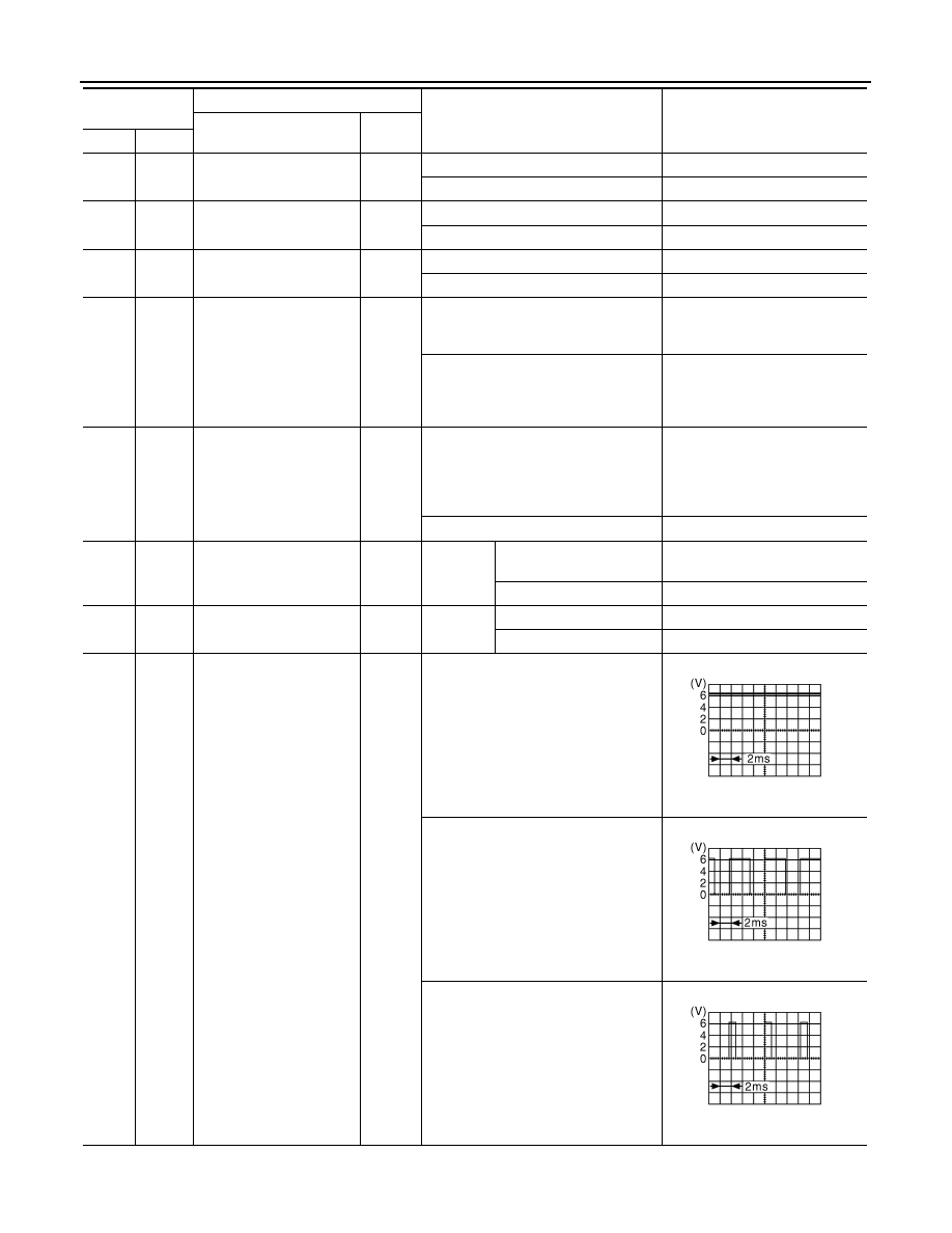
76
(SB)
Ground
Power generation com-
mand signal
Output
Ignition switch ON
6.3 V
40% is set on “ACTIVE TEST”, “AL-
TERNATOR DUTY” of “ENGINE”
3.8 V
80% is set on “ACTIVE TEST”, “AL-
TERNATOR DUTY” of “ENGINE”
1.4 V
Terminal No.
(Wire color)
Description
Condition
Value
(Approx.)
Signal name
Input/
Output
+
−
JPMIA0001GB
JPMIA0002GB
JPMIA0003GB
Revision: 2012 October
2013 Murano CrossCabriolet