Murano Cross Cabriolet Z51 (2013 year). Manual - part 46


  Index      Manuals     Murano Cross Cabriolet Z51 (2013 year) - Service and Repair Manual


Search            copyright infringement  


Content      ..     44      45      46      47     ..


Murano Cross Cabriolet Z51 (2013 year). Manual - part 46


HAC-16

< SYSTEM DESCRIPTION >

[AUTOMATIC AIR CONDITIONING]

SYSTEM

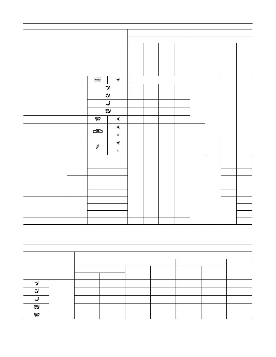
*: Inlet status is displayed by indicator during activating automatic control

AIR DISTRIBUTION

Fail-safe

INFOID:0000000008460636

FAIL-SAFE FUNCTION

Switch/Dial position

Door position

Mode door

In

ta

ke

 do

or

Up

pe

r ve

nt

ila

to

r do

or

Air mix door

V

e

n

tila

to

r do

or

M

ax

. co

ol do

or

De

fros

te

r do

or

Fo

ot

 do

or

(Driver side)

(Pa

sse

ng

er s

id

e

)

AUTO switch

AUTO

MODE switch

A

A

A

A

B

B

A

B

C

B

B

C

C

B

B

B

DEF switch

C

C

C

A

Intake switch

*

A

B

UPPER VENT switch

A – B

C

Temperature control 
dial (Driver side)

DUAL 
switch: 
OFF

60

°

F

A

A

61

°

F – 89 

°

F

AUTO

AUTO

90

°

F

B

B

DUAL 
switch: 
ON

60

°

F

A

61

°

F – 89 

°

F

AUTO

90

°

F

B

Temperature control dial (Passen-
ger side)

60

°

F

A

61

°

F – 89 

°

F

AUTO

90

°

F

B

ON·OFF switch

OFF

C

B

B

C

Discharge air flow

MODE/DEF 

set position

Condition

Air outlet/distribution

Ventilator

Foot

Defroster

Front

Upper

Rear

Front

Rear

Center

Side

• DUAL 

switch: 
OFF

• UPPER 

VENT 
switch: 
ON

40%

41%

8%

11%

18%

24%

10%

17%

23%

8%

12%

12%

15.5%

27.5%

12%

21%

11%

11%

14%

24%

11%

29%

11%

10.5%

12.5%

66%

Revision: 2012 October

2013 Murano CrossCabriolet

SYSTEM

HAC-17

< SYSTEM DESCRIPTION >

[AUTOMATIC AIR CONDITIONING]

C

D

E

F

G

H

J

K

L

M

A

B

HAC

N

O

P

When a communication error between A/C auto amp. and AV control unit and preset switch continued for
approximately 30 seconds or more, air conditioning is controlled under the following conditions.

Set temperature

: Setting before communication error occurs

Air outlet

: Automatic control

Air flow

: Automatic control

Air inlet

: Fresh air intake (FRE)

A/C switch

: ON

Revision: 2012 October

2013 Murano CrossCabriolet

HAC-18

< SYSTEM DESCRIPTION >

[AUTOMATIC AIR CONDITIONING]

OPERATION

OPERATION

Switch Name and Function

INFOID:0000000008460637

OPERATION AND DISPLAY OF AUTOMATIC AIR CONDITIONING SYSTEM

Display: Display unit

BOSE audio with navigation

BOSE audio without navigation

• Air conditioning operation status is indicated on display in display unit.
• When “STATUS” on multifunction switch is pressed while air conditioning is in the ON position the display

changes to state indication display of air conditioning system. When air conditioning is operated while navi-
gation system or audio system is displayed, air conditioning state is indicated in the lower portion of display
for several seconds.

• When MODE switch is pressed while air conditioning is in the OFF position, state indication display is indi-

cated for several seconds.

Operation: Preset switch

JMIIA1887GB

JMIIA1888GB

1.

Temperature control dial (driver side) 2.

AUTO switch

3.

DEF switch

4.

ON·OFF switch

5.

DUAL switch

6.

Temperature control dial (passenger 
side)

JMIIA1889ZZ

Revision: 2012 October

2013 Murano CrossCabriolet

OPERATION

HAC-19

< SYSTEM DESCRIPTION >

[AUTOMATIC AIR CONDITIONING]

C

D

E

F

G

H

J

K

L

M

A

B

HAC

N

O

P

7.

MODE switch

8.

UPPER VENT switch

9.

Fan control dial

10. Intake switch

11.

A/C switch

Switch name

Function

Temperature control 
dial (driver side)

Setting temperature can be set according to dial operation within a range between 60

°

F – 90

°

F at a rate 

of 1

°

F per adjustment.

• Clock wise rotation: Setting temperature increases
• Counterclockwise rotation: Setting temperature decreases
NOTE:
When air conditioning is OFF, setting temperature can be set only while air conditioning status screen 
(only when MODE switch is pressed) is indicated.

AUTO switch

• AUTO switch indicator turns ON and air conditioning becomes the following status, when this switch is 

pressed while air conditioning is ON.

- Air outlet: Automatic control
- Air flow: Automatic control
- Air inlet: Automatic control
- A/C switch: ON
• Air conditioning turns ON and operates according to the following status, when this switch is pressed 

while air conditioning is OFF. (AUTO switch indicator turns ON)

- Air outlet: Automatic control
- Air flow: Automatic control
- Air inlet: Automatic control
- A/C switch: ON
NOTE:
When air outlet or air flow is manually operated while AUTO switch indicator is ON, AUTO switch indica-
tor turns OFF. However, automatic control continues for other functions than air outlet or air flow.

DEF switch

DEF mode (switch indicator) changes between ON 

 OFF each time switch is pressed.

• When this switch is pressed while air conditioning is ON
- Air conditioning becomes the following status when DEF mode is turned ON.
• Air outlet: DEF
• Air flow: Settings set before DEF mode is turned ON
• Air inlet: Fresh air intake
• A/C switch: ON
- Air conditioning becomes the following status when DEF mode is turned OFF.
• Air outlet: Settings set before DEF mode is turned ON
• Air flow: Settings set before DEF mode is turned OFF
• Air inlet: Settings set before DEF mode is turned OFF
• A/C switch: Settings set before DEF mode is turned OFF
• When this switch is pressed while air conditioning is OFF
- Air conditioning turns ON and operates in the following status, when DEF mode is turned ON.
• Air outlet: DEF
• Air flow: Automatic control
• Air inlet: Fresh air intake
• A/C switch: ON
- Air conditioning becomes the following status when DEF mode is turned OFF.
• Air outlet: Automatic control
• Air flow: Settings set before DEF mode is turned OFF
• Air inlet: Settings set before DEF mode is turned OFF
• A/C switch: Settings set before DEF mode is turned OFF
NOTE:
When DEF mode is turned ON while AUTO switch indicator is turned ON, AUTO switch indicator turns 
OFF. However, automatic air flow control continues.

ON·OFF switch

Air conditioning turns ON 

 OFF each time this switch is pressed.

• When this switch is pressed while air conditioning is ON
- Air conditioning turns OFF and becomes the following status, when this switch is pressed.
• Air outlet: FOOT
• Air flow: OFF
• Air inlet: Fresh air intake
• A/C switch: OFF
• When this switch is pressed while air conditioning is OFF
- Air conditioning turns ON and operates according to the settings set before air conditioning is turned 

OFF, when this switch is pressed.

Revision: 2012 October

2013 Murano CrossCabriolet

HAC-20

< SYSTEM DESCRIPTION >

[AUTOMATIC AIR CONDITIONING]

OPERATION

DUAL switch

Left and right ventilation temperature separately control (switch indicator) changes between ON 

 OFF 

each time this switch is pressed while blower motor is operated.
NOTE:
• Setting temperature for passenger side is the same as that for driver side when left and right ventilation 

temperature separately control is OFF.

• DUAL switch operation is not accepted when DEF mode is ON.

Temperature control 
dial (passenger side)

• Left and right ventilation temperature separately control (DUAL switch indicator) turns ON according 

to dial operation. Air flow temperature of passenger side can be changed without changing air flow 
temperature of driver side.

• Setting temperature can be set according to dial operation within a range between 60

°

F – 90

°

F at a 

rate of 1

°

F per adjustment.

- Clock wise rotation: Setting temperature increases
- Counterclockwise rotation: Setting temperature decreases
NOTE:
• When air conditioning is OFF, setting temperature can be set only while air conditioning status screen 

(only when MODE switch is pressed) is indicated.

• Temperature control dial (passenger side) operation is not accepted when DEF mode is ON.

MODE switch

Air outlet changes from VENT

 B/L 

 FOOT 

 D/F 

 VENT each time this switch is pressed.

NOTE:
• Air outlet can be changed when air conditioning is in OFF status.
• Automatic air outlet control is cancelled (AUTO switch indicator turns OFF), when MODE switch is 

pressed while AUTO switch indicator is ON.

UPPER VENT switch

Upper ventilator control (switch indicator) changes between ON 

 OFF each time this switch is pressed 

while blower motor is operated.
NOTE:
• When air conditioning is OFF, upper ventilator control can be changed only while air conditioning status 

screen (only when MODE switch is pressed) is indicated.

• UPPER VENT switch operation is not accepted when DEF mode is ON.

Fan control dial

• Air flow can be set within a range between 1st – 7th speed according to dial operation.
- Clock wise rotation: Air flow increases
- Counterclockwise rotation: Air flow decreases
• Air conditioning turns ON and operates according to the following status, when this switch is pressed 

while air conditioning is OFF.

- Air outlet: Automatic control
- Air flow: Automatic control
- Air inlet: Settings set before fan control dial is operated
- A/C switch: Settings set before air conditioning is turned OFF
NOTE:
Automatic air flow control is cancelled (AUTO switch indicator turns OFF), when fan control dial is oper-
ated while AUTO switch indicator is ON.

Intake switch

• Air inlet changes between recirculation (REC) 

 fresh air intake (FRE) each time this switch is 

pressed.

- Switch indicator ON: Recirculation
- Switch indicator OFF: Fresh air intake
• Switch indicator blinks 2 times and air inlet is set to automatic control when switch is pressed and held 

for 2 seconds or more. (Switch indicator indicates air inlet status during automatic control)

NOTE:
• Air inlet can be changed when air conditioning is in OFF status.
• REC switch operation is not accepted when air outlet is D/F or DEF.
• A/C switch turns ON when REC switch is turned ON while A/C switch is OFF.

A/C switch

Compressor control (switch indicator) changes between ON 

 OFF each time this switch is pressed 

while blower motor is operated.
NOTE:
• A/C switch cannot be turned ON when blower motor is OFF.
• A/C switch cannot be turned OFF when air outlet is D/F or DEF.
• Air inlet changes to fresh air intake when A/C switch is turned OFF while air inlet is set to recirculation.

Switch name

Function

Revision: 2012 October

2013 Murano CrossCabriolet

DIAGNOSIS SYSTEM (A/C AUTO AMP.)

HAC-21

< SYSTEM DESCRIPTION >

[AUTOMATIC AIR CONDITIONING]

C

D

E

F

G

H

J

K

L

M

A

B

HAC

N

O

P

DIAGNOSIS SYSTEM (A/C AUTO AMP.)

Description

INFOID:0000000008460638

Air conditioning system performs self-diagnosis, operation check, function diagnosis, and various settings
using diagnosis function of each control unit.

CONSULT Function

INFOID:0000000008460639

CONSULT performs the following functions via CAN communication with A/C auto amp. 

NOTE:
Diagnosis should be performed with engine running. Door motor operation speeds become slower and NO
results may be returned even for normal operation if battery voltage drops below 12 V during self-diagnosis. 

ECU IDENTIFICATION

Part number of A/C auto amp. can be checked.

SELF-DIAGNOSIS RESULTS

Diagnosis result that is judged by A/C auto amp. can be checked. Refer to 

HAC-26, "DTC Index"

.

DATA MONITOR

Input/output signal of A/C auto amp. can be checked.
NOTE:
The following table includes information (items) inapplicable to this vehicle. For information (items) applicable
to this vehicle, refer to CONSULT display items.

Display item list

ECU

Diagnostic item

(CONSULT)

A/C auto amp.

HVAC

Self Diagnostic Result

Data Monitor

Active Test

Work support

AV control unit

MULTI AV

Self Diagnostic Result

Multi AV system on board diagnosis function

ECM

ENGINE

Self Diagnostic Result

Data Monitor

IPDM E/R

IPDM E/R

Self Diagnostic Result

Data Monitor

Auto active test

Diagnostic mode

Description

Ecu Identification

Displays the part number of A/C auto amp. 

Self Diagnostic Result

Displays the diagnosis results judged by A/C auto amp. 

Data Monitor

Displays the input/output signal of A/C auto amp. 

Active Test

The signals used to activate each device are forcibly supplied from A/C auto amp. 

Work support

Changes the setting for each setting function.

Monitor item [Unit]

Description

AMB TEMP SEN

[

°

C (

°

F)]

Ambient temperature value converted from ambient sensor signal received from ambi-
ent sensor 

IN-VEH TEMP

[

°

C (

°

F)]

In-vehicle temperature value converted from in-vehicle sensor signal received from in-
vehicle sensor

INT TEMP SEN

[

°

C (

°

F)]

Evaporator fin temperature value converted from intake sensor signal received from in-
take sensor 

Revision: 2012 October

2013 Murano CrossCabriolet

HAC-22

< SYSTEM DESCRIPTION >

[AUTOMATIC AIR CONDITIONING]

DIAGNOSIS SYSTEM (A/C AUTO AMP.)

ACTIVE TEST

The signals used to activate each device forcibly supplied from A/C auto amp. operation check of air condi-
tioning system can be performed.

Check each output device

*: Position of mode door motor is set to the status of automatic control that is selected by foot position setting
trimmer. Refer to 

HAC-36, "Foot Position Setting Trimmer"

.

NOTE:
Perform the inspection of each output device after starting the engine because the compressor is operated. 

WORK SUPPORT

Setting change of each setting functions and automatic adjustment of components can be performed.

SUNLOAD SEN

[w/m

2

]

Sunload value converted from sunload sensor signal received from sunload sensor 

AMB SEN CAL

[

°

C (

°

F)]

Ambient temperature value calculated by A/C auto amp.

IN-VEH CAL

[

°

C (

°

F)]

In-vehicle temperature value calculated by A/C auto amp.

INT TEMP CAL

[

°

C (

°

F)]

Evaporator fin temperature value calculated by A/C auto amp.

SUNL SEN CAL

[w/m

2

]

Sunload value calculated by A/C auto amp.

COMP REQ SIG

[On/Off]

Displays A/C ON signal ON/OFF status transmitted to ECM.

FAN REQ SIG

[On/Off]

Displays blower fan ON signal ON/OFF status transmitted to ECM.

FAN DUTY

Duty ratio of blower motor judged by A/C auto amp.

XM

Target discharge air temperature judged by A/C auto amp. depending on the tempera-
ture setting and the value from each sensor

ENG COOL TEMP

[

°

C (

°

F)]

Engine coolant temperature signal value received from ECM via CAN communication

VEHICLE SPEED

[km/h

(mph)]

Vehicle speed signal value received from combination meter via CAN communication

Monitor item [Unit]

Description

Test item

Description

HVAC TEST

The operation check of air conditioning system can be performed by selecting the mode. 
Refer to the following table for the conditions of each mode. 

Test item

MODE 1

MODE 2

MODE 3

MODE 4

MODE 5

MODE 6

MODE 7

Mode door motor position

VENT

VENT

B/L

B/L

FOOT

*

D/F

DEF

Intake door motor position

REC

REC

20% FRE

20% FRE

FRE

FRE

FRE

Air mix door motor (driver side/
passenger side) position

FULL COLD

FULL HOT

FULL COLD

FULL HOT

FULL HOT

FULL HOT

FULL HOT

Blower motor (duty ratio)

35%

35%

61%

61%

91%

91%

35%

Magnet clutch

ON

ON

ON

ON

OFF

OFF

ON

Upper ventilator door motor 
position

OPEN

CLOSE

OPEN

CLOSE

CLOSE

CLOSE

CLOSE

Work item

Description

Refer to

TEMP SET CORRECT

Setting change of temperature setting trimmer can be performed. 

HAC-35, "Temperature 
Setting Trimmer"

REC MEMORY SET

Setting change of inlet port memory function (REC) can be per-
formed. 

HAC-35, "Inlet Port Mem-
ory Function (REC)"

FRE MEMORY SET

Setting change of inlet port memory function (FRE) can be per-
formed. 

HAC-36, "Inlet Port Mem-
ory Function (FRE)"

BLOWER SET

Setting change of foot position setting trimmer can be performed. 

HAC-36, "Foot Position 
Setting Trimmer"

Revision: 2012 October

2013 Murano CrossCabriolet

DIAGNOSIS SYSTEM (A/C AUTO AMP.)

HAC-23

< SYSTEM DESCRIPTION >

[AUTOMATIC AIR CONDITIONING]

C

D

E

F

G

H

J

K

L

M

A

B

HAC

N

O

P

NOTE:
When the battery cable is disconnected from the negative terminal or when the battery voltage becomes 10 V
or less, the setting of WORK SUPPORT may be cancelled. 

Revision: 2012 October

2013 Murano CrossCabriolet

HAC-24

< ECU DIAGNOSIS INFORMATION >

[AUTOMATIC AIR CONDITIONING]

A/C AUTO AMP.

ECU DIAGNOSIS INFORMATION

A/C AUTO AMP.

Reference Value

INFOID:0000000008460640

CONSULT DATA MONITOR REFERENCE VALUES

NOTE:
The following table includes information (items) inapplicable to this vehicle. For information (items) applicable
to this vehicle, refer to CONSULT display items.

TERMINAL LAYOUT

PHYSICAL VALUES

Monitor item

Condition

Value/Status

AMB TEMP SEN

Ignition switch ON

Equivalent to ambient tem-
perature

IN-VEH TEMP

Ignition switch ON

Equivalent to in-vehicle tem-
perature

INT TEMP SEN

Ignition switch ON

Equivalent to evaporator fin 
temperature

SUNLOAD SEN

Ignition switch ON

Equivalent to sunload 
amount

AMB SEN CAL

Ignition switch ON

Equivalent to ambient tem-
perature

IN-VEH CAL

Ignition switch ON

Equivalent to in-vehicle tem-
perature

INT TEMP CAL

Ignition switch ON

Equivalent to evaporator fin 
temperature

SUNL SEN CAL

Ignition switch ON

Equivalent to sunload 
amount

COMP REQ SIG

Engine: Run at idle after 
warming up 

A/C switch: ON
(Compressor operation sta-
tus) 

On

A/C switch: OFF

Off

FAN REQ SIG

Engine: Run at idle after 
warming up 

Blower motor: ON

On

Blower motor: OFF

Off

FAN DUTY

Engine: Run at idle after 
warming up 

Blower motor: ON

25 – 81

Blower motor: OFF

0

XM

Ignition switch ON

Value according to target air 
flow temperature

ENG COOL TEMP

Ignition switch ON

Equivalent to engine coolant 
temperature

VEHICLE SPEED

Driving

Equivalent to speedometer 
reading

JMIIA0690ZZ

Revision: 2012 October

2013 Murano CrossCabriolet

A/C AUTO AMP.

HAC-25

< ECU DIAGNOSIS INFORMATION >

[AUTOMATIC AIR CONDITIONING]

C

D

E

F

G

H

J

K

L

M

A

B

HAC

N

O

P

Fail-safe

INFOID:0000000008460641

FAIL-SAFE FUNCTION

Terminal No.

(Wire color)

Description

Condition

Value

(Approx.)

+

Signal name

Input/

Output

1

(L)

CAN-H

Input/

Output

2

(P)

CAN-L

Input/

Output

10

(L)

Ground

LAN signal

Input/

Output

Ignition switch ON

11

(R)

Ground

Door motor power supply

Output

Ignition switch ON

12 V

15

(O)

Ground

Sunload sensor signal

Input

Ignition switch ON

0 – 4.8 V

Output voltage varies with sun-

load amount

16

(G)

Ground

Intake sensor signal

Input

Ignition switch ON

0 – 4.8 V

Output voltage varies with evapo-

rator fin temperature

17

(R)

Ground

ACC power supply

Ignition switch ON

Battery voltage

19

(B)

Ground

Ground

Ignition switch ON

0 V

20

(G)

Ground

Ignition power supply

Ignition switch ON

Battery voltage

32

(L)

Ground

Blower motor control signal

Output

• Ignition switch ON
• Fan speed: 1st speed 

(manual)

34

(P)

Ground

A/C auto amp. connection rec-
ognition signal

Output

Ignition switch ON

5 V

35

(L)

Ground

Ambient sensor signal

Input

Ignition switch ON

0 – 4.8 V

Output voltage varies with ambi-

ent temperature

36

(LG)

Ground

In-vehicle sensor signal

Input

Ignition switch ON

0 – 4.8 V

Output voltage varies with in-ve-

hicle temperature

37

(Y)

Ground

Sensor ground

Ignition switch ON

0 V

39

(B)

Ground

Ground

Ignition switch ON

0 V

40

(Y)

Ground

Battery power supply

Ignition switch OFF

Battery voltage

SJIA1453J

JSIIA0096ZZ

Revision: 2012 October

2013 Murano CrossCabriolet

HAC-26

< ECU DIAGNOSIS INFORMATION >

[AUTOMATIC AIR CONDITIONING]

A/C AUTO AMP.

When a communication error between A/C auto amp. and AV control unit and preset switch continued for
approximately 30 seconds or more, air conditioning is controlled under the following conditions.

DTC Index

INFOID:0000000008460642

*: Perform self-diagnosis under sunshine. When performing indoors, aim a light (more than 60 W) at sunload
sensor, otherwise self-diagnosis indicates even though the sunload sensor is functioning normally.
NOTE:
If all of door motor DTCs (B2632, B2633, B2634, B2635, B2636, B2637, B2638, B2639, B263D, B263E,
B263F, B2654, B2655, B2661, B2662, and B2663) are detected, check “DOOR MOTOR” circuit. Refer to

HAC-65, "Diagnosis Procedure"

.

Set temperature

: Setting before communication error occurs

Air outlet

: Automatic control

Air flow

: Automatic control

Air inlet

: Fresh air intake (FRE)

A/C switch

: ON

DTC

Items

(CONSULT screen terms)

Reference

U1000

CAN COMM CIRCUIT

HAC-37, "DTC Logic"

U1010

CONTROL UNIT (CAN)

HAC-38, "DTC Logic"

B2578

IN-VEHICLE SENSOR

HAC-39, "DTC Logic"

B2579

IN-VEHICLE SENSOR

HAC-39, "DTC Logic"

B257B

AMBIENT SENOR

HAC-41, "DTC Logic"

B257C

AMBIENT SENOR

HAC-41, "DTC Logic"

B2581

INTAKE SENSOR

HAC-43, "DTC Logic"

B2582

INTAKE SENSOR

HAC-43, "DTC Logic"

B2630

*

SUNLOAD SENSOR

HAC-45, "DTC Logic"

B2631

*

SUNLOAD SENSOR

HAC-45, "DTC Logic"

B2632

DR AIR MIX DOOR MOT

HAC-48, "DTC Logic"

B2633

DR AIR MIX DOOR MOT

HAC-48, "DTC Logic"

B2634

PASS AIR MIX DOOR MOT

HAC-51, "DTC Logic"

B2635

PASS AIR MIX DOOR MOT

HAC-51, "DTC Logic"

B2636

DR VENT DOOR FAIL

HAC-54, "DTC Logic"

B2637

DR B/L DOOR FAIL

HAC-54, "DTC Logic"

B2638

DR D/F1 DOOR FAIL

HAC-54, "DTC Logic"

B2639

DR DEF DOOR FAIL

HAC-54, "DTC Logic"

B263D

FRE DOOR FAIL

HAC-57, "DTC Logic"

B263E

20P FRE DOOR FAIL

HAC-57, "DTC Logic"

B263F

REC DOOR FAIL

HAC-57, "DTC Logic"

B2654

D/F2 DOOR FAIL

HAC-54, "DTC Logic"

B2655

B/L2 DOOR FAIL

HAC-54, "DTC Logic"

B2661

UPPER VENT DOOR MOT

HAC-60, "DTC Logic"

B2662

UPPER VENT DOOR MOT

HAC-60, "DTC Logic"

B2663

UPPER VENT DOOR MOT

HAC-60, "DTC Logic"

Revision: 2012 October

2013 Murano CrossCabriolet

ECM, IPDM E/R

HAC-27

< ECU DIAGNOSIS INFORMATION >

[AUTOMATIC AIR CONDITIONING]

C

D

E

F

G

H

J

K

L

M

A

B

HAC

N

O

P

ECM, IPDM E/R

List of ECU Reference

INFOID:0000000008460643

ECU

Reference

ECM

EC-74, "Reference Value"

EC-88, "Fail-safe"

EC-90, "DTC Inspection Priority Chart"

EC-91, "DTC Index"

IPDM E/R

PCS-15, "Reference Value"

PCS-21, "Fail-safe"

PCS-23, "DTC Index"

Revision: 2012 October

2013 Murano CrossCabriolet

HAC-28

< WIRING DIAGRAM >

[AUTOMATIC AIR CONDITIONING]

AUTOMATIC AIR CONDITIONING SYSTEM

WIRING DIAGRAM

AUTOMATIC AIR CONDITIONING SYSTEM

Wiring Diagram

INFOID:0000000008460644

For connector terminal arrangements, harness layouts, and alphabets in a 

 (option abbreviation; if not

described in wiring diagram), refer to 

GI-12, "Connector Information"

.

JRIWC0507GB

Revision: 2012 October

2013 Murano CrossCabriolet

AUTOMATIC AIR CONDITIONING SYSTEM

HAC-29

< WIRING DIAGRAM >

[AUTOMATIC AIR CONDITIONING]

C

D

E

F

G

H

J

K

L

M

A

B

HAC

N

O

P

JRIWC0508GB

Revision: 2012 October

2013 Murano CrossCabriolet

HAC-30

< BASIC INSPECTION >

[AUTOMATIC AIR CONDITIONING]

DIAGNOSIS AND REPAIR WORK FLOW

BASIC INSPECTION

DIAGNOSIS AND REPAIR WORK FLOW

Work Flow

INFOID:0000000008460645

OVERALL SEQUENCE

DETAILED FLOW

JMKIA8652GB

Revision: 2012 October

2013 Murano CrossCabriolet

DIAGNOSIS AND REPAIR WORK FLOW

HAC-31

< BASIC INSPECTION >

[AUTOMATIC AIR CONDITIONING]

C

D

E

F

G

H

J

K

L

M

A

B

HAC

N

O

P

1.

GET INFORMATION FOR SYMPTOM

1.

Get detailed information from the customer about the symptom (the condition and the environment when
the incident/malfunction occurs).

2.

Check operation condition of the function that is malfunctioning.

>> GO TO 2.

2.

CHECK DTC

1.

Check DTC.

2.

Perform the following procedure if DTC is detected.

-

Record DTC and freeze frame data (Print them out using CONSULT.)

-

Erase DTC.

-

Study the relationship between the cause detected by DTC and the symptom described by the customer.

3.

Check related service bulletins for information.

Are any symptoms described and any DTC detected?

Symptom is described, DTC is detected>>GO TO 3.
Symptom is described, DTC is not detected>>GO TO 4.
Symptom is not described, DTC is detected>>GO TO 5.

3.

CONFIRM THE SYMPTOM

Try to confirm the symptom described by the customer.
Also study the normal operation and fail-safe related to the symptom.
Verify relation between the symptom and the condition when the symptom is detected.

>> GO TO 5.

4.

CONFIRM THE SYMPTOM

Try to confirm the symptom described by the customer.
Verify relation between the symptom and the condition when the symptom is detected.

>> GO TO 6.

5.

PERFORM DTC CONFIRMATION PROCEDURE

Perform DTC CONFIRMATION PROCEDURE for the detected DTC, and then check that DTC is detected
again. At this time, always connect CONSULT to the vehicle, and check self diagnostic results in real time.
If two or more DTCs are detected, refer to DTC INSPECTION PRIORITY CHART, and determine trouble diag-
nosis order.
NOTE:
• Freeze frame data is useful if the DTC is not detected.
• Perform Component Function Check if DTC CONFIRMATION PROCEDURE is not included on Service

Manual. This simplified check procedure is an effective alternative though DTC cannot be detected during
this check.
If the result of Component Function Check is NG, it is the same as the detection of DTC by DTC CONFIR-
MATION PROCEDURE.

Is DTC detected?

YES

>> GO TO 7.

NO

>> Check according to 

GI-40, "Intermittent Incident"

.

6.

DETECT MALFUNCTIONING SYSTEM BY SYMPTOM DIAGNOSIS

Detect malfunctioning system according to SYMPTOM DIAGNOSIS based on the confirmed symptom in step
4, and determine the trouble diagnosis order based on possible causes and symptom.

Is the symptom described?

YES

>> GO TO 7.

NO

>> Monitor input data from related sensors or check voltage of related module terminals using CON-

SULT.

7.

DETECT MALFUNCTIONING PART BY DIAGNOSIS PROCEDURE

Revision: 2012 October

2013 Murano CrossCabriolet


Content      ..     44      45      46      47     ..