Murano Cross Cabriolet Z51 (2013 year). Manual - part 40
HOW TO USE THIS MANUAL
GI-5
< HOW TO USE THIS MANUAL >
C
D
E
F
G
H
I
J
K
L
M
B
GI
N
O
P
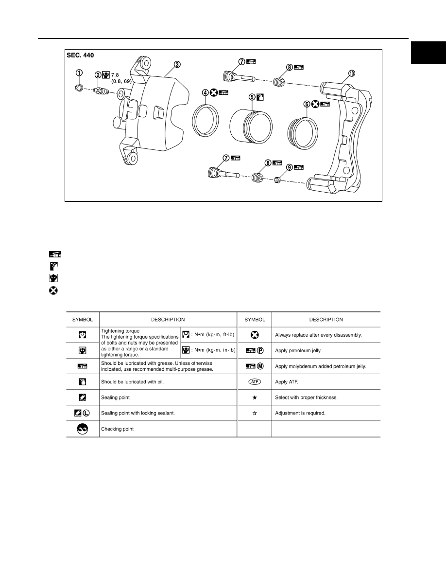
SYMBOLS
1.
Cap
2.
Bleeder valve
3.
Cylinder body
4.
Piston seal
5.
Piston
6.
Piston boot
7.
Sliding pin
8.
Sliding pin boot
9.
Bushing
10.
Torque member
: Apply rubber grease.
: Apply brake fluid.
: N·m (kg-m, in-lb)
: Always replace after every disassembly
JPFIA0511GB
SAIA0749E
Revision: 2012 October
2013 Murano CrossCabriolet