Murano Cross Cabriolet Z51 (2013 year). Manual - part 35
EXL-78
< REMOVAL AND INSTALLATION >
[XENON TYPE]
HEADLAMP AIMING SWITCH
HEADLAMP AIMING SWITCH
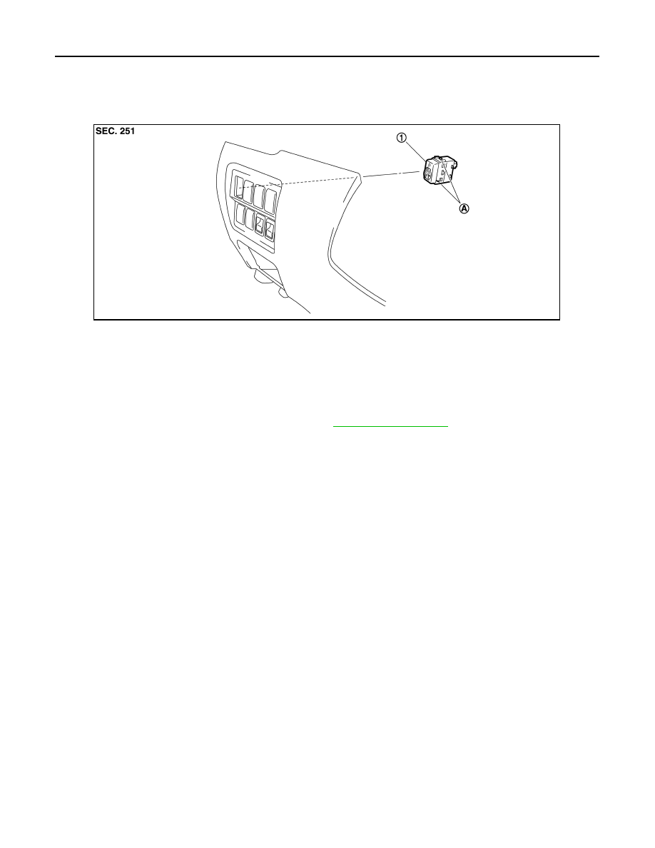
Exploded View
INFOID:0000000008460343
Removal and Installation
INFOID:0000000008460344
REMOVAL
1.
Remove the instrument driver lower panel. Refer to
.
2.
Disengage the pawls. And remove the headlamp aiming switch.
INSTALLATION
Install in the reverse order of removal.
1.
Headlamp aiming switch
A.
Pawls
JPLIA0820ZZ
Revision: 2012 October
2013 Murano CrossCabriolet