Murano Cross Cabriolet Z51 (2013 year). Manual - part 34
EXL-62
< SYMPTOM DIAGNOSIS >
[XENON TYPE]
BOTH SIDE HEADLAMPS (LO) ARE NOT TURNED ON
BOTH SIDE HEADLAMPS (LO) ARE NOT TURNED ON
Description
INFOID:0000000008460320
Both side headlamps (LO) are not turned ON in any condition.
Diagnosis Procedure
INFOID:0000000008460321
1.
COMBINATION SWITCH INSPECTION
Check the combination switch. Refer to
Is the combination switch normal?
YES
>> GO TO 2.
NO
>> Repair or replace the malfunctioning part.
2.
CHECK HEADLAMP (LO) REQUEST SIGNAL INPUT
CONSULT DATA MONITOR
1.
Select “HL LO REQ” of IPDM E/R data monitor item.
2.
With operating the lighting switch, check the monitor status.
Is the item status normal?
YES
>> GO TO 3.
NO
>> Replace BCM. Refer to
BCS-77, "Removal and Installation"
3.
HEADLAMP (LO) CIRCUIT INSPECTION
Check the headlamp (LO) circuit. Refer to
EXL-39, "Component Function Check"
.
Is the headlamp (LO) circuit normal?
YES
>> Replace IPDM E/R.
NO
>> Repair or replace the malfunctioning part.
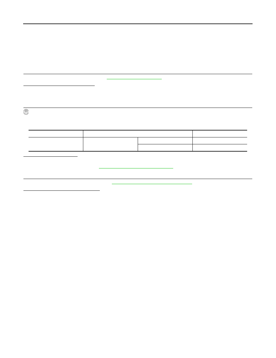
Monitor item
Condition
Monitor status
HL LO REQ
Lighting switch
2ND
ON
OFF
OFF
Revision: 2012 October
2013 Murano CrossCabriolet