Nissan Murano Z51 (2013 year). Manual - part 88


  Index      Manuals     Nissan Murano Z51 (2013 year) - Service and Repair Manual


Search            copyright infringement  


Content      ..     86      87      88      89     ..


Nissan Murano Z51 (2013 year). Manual - part 88


ENGINE SPEED SIGNAL CIRCUIT

STC-9

< DTC/CIRCUIT DIAGNOSIS >

C

D

E

F

H

I

J

K

L

M

A

B

STC

N

O

P

ENGINE SPEED SIGNAL CIRCUIT

Description

INFOID:0000000008455035

ECM sends engine speed signal to power steering control unit.

Diagnosis Procedure

INFOID:0000000008455036

1.

PERFORM ECM SELF-DIAGNOSIS

With CONSULT

1.

Turn the ignition switch ON.

CAUTION:

Never start the engine

2.

Perform “ENGINE” self-diagnosis. Refer to 

EC-128, "CONSULT Function"

.

Is any DTC detected?

YES

>> Check the DTC.

NO

>> GO TO 2.

2.

CHECK HARNESS BETWEEN ECM AND POWER STEERING CONTROL UNIT

1.

Turn the ignition switch OFF.

2.

Disconnect ECM harness connectors.

3.

Disconnect power steering control unit harness connector.

4.

Check continuity between ECM harness connector and power steering control unit harness connector.

5.

Check continuity between power steering control unit harness connector and ground.

Is the inspection result normal?

YES

>> GO TO 3.

NO

>> Repair or replace damaged parts.

3.

CHECK ENGINE SPEED SIGNAL (1)

1.

Connect ECM harness connectors.

2.

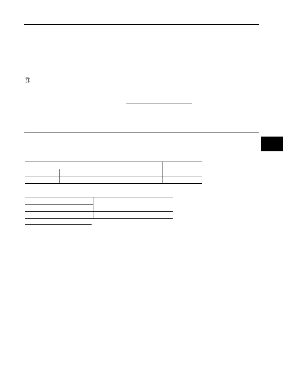
Check signal between ECM harness connector and ground with oscilloscope.

ECM

Power steering control unit

Continuity

Connector

Terminal

Connector

Terminal

E16

94

M61

10

Existed

Power steering control unit

Continuity

Connector

Terminal

M61

10

Ground

Not existed

Revision: 2012 September

2013 MURANO

STC-10

< DTC/CIRCUIT DIAGNOSIS >

ENGINE SPEED SIGNAL CIRCUIT

Is the inspection result normal?

YES

>> GO TO 4.

NO

>> Replace ECM. Refer to 

EC-16, "ADDITIONAL SERVICE WHEN REPLACING CONTROL UNIT :

Description"

.

4.

CHECK ENGINE SPEED SIGNAL (2)

1.

Turn the ignition switch OFF.

2.

Connect power steering control unit harness connector.

3.

Check signal between power steering control unit harness connector and ground with oscilloscope.

Is the inspection result normal?

YES

>> GO TO 5.

NO

>> Replace power steering control unit. Refer to 

STC-20, "Removal and Installation"

.

5.

CHECK TERMINALS AND HARNESS CONNECTORS

• Check power steering control unit pin terminals for damage or loose connection with harness connector.
• Check ECM pin terminals for damage or loose connection with harness connector.

Is the inspection result normal?

YES

>> INSPECTION END

NO

>> Repair or replace damaged parts.

ECM

Ground

Condition

Voltage

(Approx.)

Connector

Terminal

E16

94

Ground

Engine is running
• Warm-up condition
• Idle speed

Engine is running
• Warm-up condition
• Engine speed: Approx. 2,000 rpm

JMBIA0076GB

JMBIA0077GB

Power steering control unit

Condition

Voltage

(Approx.)

Connector

Terminal

M61

10

Ground

Engine is running
• Warm-up condition
• Idle speed

Engine is running
• Warm-up condition
• Engine speed: Approx. 2,000 rpm

JMBIA0076GB

JMBIA0077GB

Revision: 2012 September

2013 MURANO

VEHICLE SPEED SIGNAL CIRCUIT

STC-11

< DTC/CIRCUIT DIAGNOSIS >

C

D

E

F

H

I

J

K

L

M

A

B

STC

N

O

P

VEHICLE SPEED SIGNAL CIRCUIT

Description

INFOID:0000000008455037

Combination meter sends vehicle speed signal to power steering control unit.

Diagnosis Procedure

INFOID:0000000008455038

1.

PERFORM COMBINATION METER SELF-DIAGNOSIS

With CONSULT

1.

Turn the ignition switch ON.

CAUTION:

Never start the engine

2.

Perform “METER/M&A” self-diagnosis. Refer to 

MWI-35, "CONSULT Function (METER/M&A)"

.

Is any DTC detected?

YES

>> Check the DTC.

NO

>> GO TO 2.

2.

CHECK HARNESS BETWEEN COMBINATION METER AND POWER STEERING CONTROL UNIT

1.

Turn the ignition switch OFF.

2.

Disconnect combination meter harness connector.

3.

Disconnect power steering control unit harness connector.

4.

Check continuity between combination meter harness connector and power steering control unit harness
connector.

5.

Check continuity between power steering control unit harness connector and ground.

Is the inspection result normal?

YES

>> GO TO 3.

NO

>> Repair or replace damaged parts.

3.

CHECK VEHICLE SPEED SIGNAL (1)

1.

Turn the ignition switch OFF.

2.

Connect combination meter harness connector.

3.

Check combination meter input/output standard values. Refer to 

MWI-58, "Reference Value"

.

Is the inspection result normal?

YES

>> GO TO 4.

NO

>> Replace combination meter Refer to 

MWI-94, "Exploded View"

.

4.

CHECK VEHICLE SPEED SIGNAL (2)

1.

Turn the ignition switch OFF.

2.

Connect power steering control unit harness connector.

3.

Check signal between power steering control unit harness connector and ground with oscilloscope.

Combination meter

Power steering control unit

Continuity

Connector

Terminal

Connector

Terminal

M34

30

M61

8

Existed

Power steering control unit

Continuity

Connector

Terminal

M61

8

Ground

Not existed

Revision: 2012 September

2013 MURANO

STC-12

< DTC/CIRCUIT DIAGNOSIS >

VEHICLE SPEED SIGNAL CIRCUIT

Is the inspection result normal?

YES

>> GO TO 5.

NO

>> Replace power steering control unit. Refer to 

STC-20, "Removal and Installation"

.

5.

CHECK TERMINALS AND HARNESS CONNECTORS

• Check power steering control unit pin terminals for damage or loose connection with harness connector.
• Check combination meter pin terminals for damage or loose connection with harness connector.
Is the inspection result normal?

YES

>> INSPECTION END

NO

>> Repair or replace damaged parts.

Power steering control unit

Condition

Voltage

(Approx.)

Connector

Terminal

M61

 8

Ground

Vehicle speed: 40 km/h (25 MPH)

CAUTION:

Check air pressure of tire under 
standard condition.

NOTE:
The maximum voltage varies de-
pending on the specification (desti-
nation unit).

JSNIA0015GB

Revision: 2012 September

2013 MURANO

POWER STEERING CONTROL UNIT

STC-13

< ECU DIAGNOSIS INFORMATION >

C

D

E

F

H

I

J

K

L

M

A

B

STC

N

O

P

ECU DIAGNOSIS INFORMATION

POWER STEERING CONTROL UNIT

Reference Value

INFOID:0000000008455039

TERMINAL LAYOUT

PHYSICAL VALUES

JSGIA0023ZZ

Terminal No.

(Wire color)

Description

Condition

Value (Approx.)

+

-

Signal name

Input/

Output

1

(Y)

Ground

Power steering solenoid 
valve voltage

Output

Vehicle speed: 0 km/h (0 MPH)
(Engine is running)

4.4 – 6.6 V

Vehicle speed: 100 km/h (62 MPH)

2.4 – 3.6 V

3

(G)

Ground

Ignition switch power 
supply

Input

Ignition switch: ON

Battery voltage

Ignition switch: OFF

0 V

5

(LG)

Ground

Power steering solenoid 
valve ground

Always

0  V

6

(B)

Ground

Ground

Always

0 V

8

(P)

Ground

Vehicle speed signal

Input

Vehicle speed: 40 km/h (25 MPH)

CAUTION:

Check air pressure of tire under 
standard condition.

NOTE:
The maximum voltage varies de-
pending on the specification 
(destination unit).

JSNIA0015GB

Revision: 2012 September

2013 MURANO

STC-14

< ECU DIAGNOSIS INFORMATION >

POWER STEERING CONTROL UNIT

CAUTION:

When using circuit tester or oscilloscope to measure voltage for inspection, be sure not to forcibly extend any connector ter-
minals.

10

(V)

Ground

Engine speed signal

Input

Engine is running
• Warm-up condition
• Idle speed

Engine is running
• Warm-up condition
• Engine speed: Approx. 2,000 rpm

Terminal No.

(Wire color)

Description

Condition

Value (Approx.)

+

-

Signal name

Input/

Output

JMBIA0076GB

JMBIA0077GB

Revision: 2012 September

2013 MURANO

POWER STEERING CONTROL UNIT

STC-15

< ECU DIAGNOSIS INFORMATION >

C

D

E

F

H

I

J

K

L

M

A

B

STC

N

O

P

Wiring Diagram - ELECTRONICALLY CONTROLLED POWER STEERING SYSTEM -

INFOID:0000000008455040

For connector terminal arrangements, harness layouts, and alphabets in a 

 (option abbreviation; if not

described in wiring diagram), refer to 

GI-12, "Connector Information"

.

Fail-Safe

INFOID:0000000008455041

EPS system

JCGWM0180GB

Revision: 2012 September

2013 MURANO

STC-16

< ECU DIAGNOSIS INFORMATION >

POWER STEERING CONTROL UNIT

• EPS system enters the fail-safe mode (that allows the steering

force to be controlled without impairing the drivability) if any of the
input/output values to/from EPS system (power steering control
unit) deviate from the standard range.
NOTE:
The system enters the fail-safe mode if the engine speed remains
at 1,500 rpm or more for over 10 seconds while the vehicle is
stopped. This is normal.

• The fail-safe function is canceled when a vehicle speed signal of 2

km/h (1.2 MPH) or more is inputted or the ignition switch is turned
OFF

ON. EPS system restores the normal operation at that time.

JSGIA0368GB

Mode

Warn-

ing lamp

DTC

Detection point (malfunction part)

Error area and root cause

Fail-safe 

function

Vehicle speed signal input

• Engine speed is 1,500 rpm or more and there is no vehicle 

speed signal input for over 10 seconds during vehicle travel.

• Vehicle speed signal has abruptly dropped from 30 km/h (19 

MPH) or more to 2 km/h (1.2 MPH) or less within 1.4 sec-
onds.

Revision: 2012 September

2013 MURANO

UNBALANCE STEERING WHEEL TURNING FORCE (TORQUE VARIATION)

STC-17

< SYMPTOM DIAGNOSIS >

C

D

E

F

H

I

J

K

L

M

A

B

STC

N

O

P

SYMPTOM DIAGNOSIS

UNBALANCE STEERING WHEEL TURNING FORCE (TORQUE VARIA-
TION)

Description

INFOID:0000000008455042

• Hard steering when fully turning the steering wheel.
• Light steering when driving at a high speed.

Diagnosis Procedure

INFOID:0000000008455043

1.

CHECK SYSTEM FOR POWER SUPPLY AND GROUND

Perform trouble diagnosis for power supply and ground. Refer to 

STC-6, "Diagnosis Procedure"

.

Is the inspection result normal?

YES

>> GO TO 2.

NO

>> Repair or replace damaged parts.

2.

CHECK SYSTEM FOR VEHICLE SPEED SIGNAL

Perform trouble diagnosis for vehicle speed signal. Refer to 

STC-11, "Diagnosis Procedure"

.

Is the inspection result normal?

YES

>> GO TO 3.

NO

>> Repair or replace damaged parts.

3.

CHECK SYSTEM FOR ENGINE SPEED SIGNAL

Perform trouble diagnosis for engine speed signal. Refer to 

STC-9, "Diagnosis Procedure"

.

Is the inspection result normal?

YES

>> GO TO 4.

NO

>> Repair or replace damaged parts.

4.

CHECK SYSTEM FOR POWER STEERING SOLENOID VALVE

Perform trouble diagnosis for power steering solenoid valve. Refer to 

STC-7, "Diagnosis Procedure"

.

Is the inspection result normal?

YES

>> Perform the symptom diagnosis for the steering system. Refer to 

ST-27, "NVH Troubleshooting

Chart"

 (With heated steering wheel), 

ST-74, "NVH Troubleshooting Chart"

 (Without heated steer-

ing wheel).

NO

>> Repair or replace damaged parts.

Revision: 2012 September

2013 MURANO

STC-18

< PRECAUTION >

PRECAUTIONS

PRECAUTION

PRECAUTIONS

FOR USA AND CANADA

FOR USA AND CANADA : Precaution for Supplemental Restraint System (SRS) "AIR 
BAG" and "SEAT BELT PRE-TENSIONER"

INFOID:0000000008455044

The Supplemental Restraint System such as “AIR BAG” and “SEAT BELT PRE-TENSIONER”, used along
with a front seat belt, helps to reduce the risk or severity of injury to the driver and front passenger for certain
types of collision. This system includes seat belt switch inputs and dual stage front air bag modules. The SRS
system uses the seat belt switches to determine the front air bag deployment, and may only deploy one front
air bag, depending on the severity of a collision and whether the front occupants are belted or unbelted.
Information necessary to service the system safely is included in the “SRS AIR BAG” and “SEAT BELT” of this
Service Manual.

WARNING:

Always observe the following items for preventing accidental activation.
• To avoid rendering the SRS inoperative, which could increase the risk of personal injury or death in

the event of a collision that would result in air bag inflation, all maintenance must be performed by
an authorized NISSAN/INFINITI dealer.

• Improper maintenance, including incorrect removal and installation of the SRS, can lead to personal

injury caused by unintentional activation of the system. For removal of Spiral Cable and Air Bag
Module, see “SRS AIR BAG”.

• Never use electrical test equipment on any circuit related to the SRS unless instructed to in this Ser-

vice Manual. SRS wiring harnesses can be identified by yellow and/or orange harnesses or harness
connectors.

PRECAUTIONS WHEN USING POWER TOOLS (AIR OR ELECTRIC) AND HAMMERS

WARNING:

Always observe the following items for preventing accidental activation.
• When working near the Air Bag Diagnosis Sensor Unit or other Air Bag System sensors with the

ignition ON or engine running, never use air or electric power tools or strike near the sensor(s) with
a hammer. Heavy vibration could activate the sensor(s) and deploy the air bag(s), possibly causing
serious injury.

• When using air or electric power tools or hammers, always switch the ignition OFF, disconnect the

battery, and wait at least 3 minutes before performing any service.

FOR MEXICO

FOR MEXICO : Precaution for Supplemental Restraint System (SRS) "AIR BAG" and 
"SEAT BELT PRE-TENSIONER"

INFOID:0000000008455045

The Supplemental Restraint System such as “AIR BAG” and “SEAT BELT PRE-TENSIONER”, used along
with a front seat belt, helps to reduce the risk or severity of injury to the driver and front passenger for certain
types of collision. Information necessary to service the system safely is included in the “SRS AIR BAG” and
“SEAT BELT” of this Service Manual.

WARNING:

Always observe the following items for preventing accidental activation.
• To avoid rendering the SRS inoperative, which could increase the risk of personal injury or death in

the event of a collision that would result in air bag inflation, all maintenance must be performed by
an authorized NISSAN/INFINITI dealer.

• Improper maintenance, including incorrect removal and installation of the SRS, can lead to personal

injury caused by unintentional activation of the system. For removal of Spiral Cable and Air Bag
Module, see “SRS AIR BAG”.

• Never use electrical test equipment on any circuit related to the SRS unless instructed to in this Ser-

vice Manual. SRS wiring harnesses can be identified by yellow and/or orange harnesses or harness
connectors.

PRECAUTIONS WHEN USING POWER TOOLS (AIR OR ELECTRIC) AND HAMMERS

WARNING:

Revision: 2012 September

2013 MURANO

PRECAUTIONS

STC-19

< PRECAUTION >

C

D

E

F

H

I

J

K

L

M

A

B

STC

N

O

P

Always observe the following items for preventing accidental activation.
• When working near the Air Bag Diagnosis Sensor Unit or other Air Bag System sensors with the

ignition ON or engine running, never use air or electric power tools or strike near the sensor(s) with
a hammer. Heavy vibration could activate the sensor(s) and deploy the air bag(s), possibly causing
serious injury.

• When using air or electric power tools or hammers, always switch the ignition OFF, disconnect the

battery, and wait at least 3 minutes before performing any service.

Revision: 2012 September

2013 MURANO

STC-20

< REMOVAL AND INSTALLATION >

POWER STEERING CONTROL UNIT

REMOVAL AND INSTALLATION

POWER STEERING CONTROL UNIT

Removal and Installation

INFOID:0000000008455046

REMOVAL

1.

Remove instrument lower panel RH. Refer to 

IP-12, "Exploded View"

.

2.

Disconnect power steering control unit connector.

3.

Remove power steering control unit.

INSTALLATION

Install in the reverse order of removal.

Revision: 2012 September

2013 MURANO

STR-1

ENGINE

C

D

E

F

G

H

I

J

K

L

M

SECTION 

STR

A

STR

N

O

P

CONTENTS

STARTING SYSTEM

BASIC INSPECTION  ....................................

2

DIAGNOSIS AND REPAIR WORK FLOW  .........

2

Work Flow (With GR8-1200 NI)  ................................

2

Work Flow (Without GR8-1200 NI)  ...........................

5

SYSTEM DESCRIPTION  ..............................

7

STARTING SYSTEM  ...........................................

7

System Diagram ........................................................

7

System Description  ...................................................

7

Component Parts Location ........................................

7

Component Description ............................................

8

DTC/CIRCUIT DIAGNOSIS  ..........................

9

B TERMINAL CIRCUIT  .......................................

9

Description ................................................................

9

Diagnosis Procedure .................................................

9

S CONNECTOR CIRCUIT  ..................................

10

Description ..............................................................

10

Diagnosis Procedure ...............................................

10

STARTING SYSTEM  ..........................................

11

Wiring Diagram - STARTING SYSTEM -  ................

11

SYMPTOM DIAGNOSIS  ..............................

12

STARTING SYSTEM  ..........................................

12

Symptom Table  .......................................................

12

PRECAUTION ..............................................

13

PRECAUTIONS .................................................

13

FOR USA AND CANADA  ..........................................

13

FOR USA AND CANADA : Precaution for Supple-
mental Restraint System (SRS) "AIR BAG" and 
"SEAT BELT PRE-TENSIONER" ............................

13

FOR MEXICO .............................................................

13

FOR MEXICO : Precaution for Supplemental Re-
straint System (SRS) "AIR BAG" and "SEAT BELT 
PRE-TENSIONER" ..................................................

13

PREPARATION ...........................................

15

PREPARATION .................................................

15

Special Service Tools  ..............................................

15

Commercial Service Tools .......................................

15

REMOVAL AND INSTALLATION  ...............

16

STARTER MOTOR  ...........................................

16

Exploded View .........................................................

16

Removal and Installation  .........................................

17

SERVICE DATA AND SPECIFICATIONS 
(SDS) ............................................................

18

SERVICE DATA AND SPECIFICATIONS 
(SDS) .................................................................

18

Starter Motor ...........................................................

18

Revision: 2012 September

2013 MURANO

STR-2

< BASIC INSPECTION >

DIAGNOSIS AND REPAIR WORK FLOW

BASIC INSPECTION

DIAGNOSIS AND REPAIR WORK FLOW

Work Flow (With GR8-1200 NI)

INFOID:0000000008888994

STARTING SYSTEM DIAGNOSIS WITH GR8-1200 NI

To test the starting system, use the following special service tool:
• GR8-1200 NI Multitasking battery and electrical diagnostic station
NOTE:
Refer to the diagnostic station Instruction Manual for proper starting system diagnosis procedures.

Revision: 2012 September

2013 MURANO

DIAGNOSIS AND REPAIR WORK FLOW

STR-3

< BASIC INSPECTION >

C

D

E

F

G

H

I

J

K

L

M

A

STR

N

P

O

OVERALL SEQUENCE

DETAILED FLOW

NOTE:
To ensure a complete and thorough diagnosis, the battery, starter motor and alternator test segments must be
done as a set from start to finish.

1.

DIAGNOSIS WITH MULTITASKING BATTERY AND ELECTRICAL DIAGNOSTIC STATION GR8-1200 NI

JMBIA4453GB

Revision: 2012 September

2013 MURANO

STR-4

< BASIC INSPECTION >

DIAGNOSIS AND REPAIR WORK FLOW

Perform the starting system test with Multitasking battery and electrical diagnostic station GR8-1200 NI. For
details and operating instructions, refer to diagnostic station Instruction Manual.
Test result

CRANKING NORMAL>>GO TO 2.
LOW VOLTAGE>>GO TO 5.
CHARGE BATTERY>>Perform  the  slow  battery charging procedure. (Initial rate of charge is 10A for 12

hours.) Perform battery test again. Refer to diagnostic station instruction manual. 

REPLACE BATTERY>>Before replacing battery, clean the battery cable clamps and battery posts. Perform

battery test again. Refer to diagnostic station instruction manual. If second test result is
“REPLACE BATTERY”, then do so. Perform battery test again to confirm repair.

2.

CRANKING CHECK

Check that the starter motor operates correctly.

Does the engine crank normally?

YES

>> GO TO 3.

NO

>> GO TO 4.

3.

ENGINE START CHECK

Check that the engine starts.
Does the engine start?

YES

>> Starter motor is OK. INSPECTION END

NO

>> Perform further diagnosis of engine mechanical or engine control system. Refer EM and EC sec-

tions. Once resolved, perform battery test again.

4.

STARTER MOTOR ACTIVATION

Check that the starter motor operates.
Does the starter motor turn?

YES

>> Check ring gear and starter motor drive pinion. Once resolved, perform battery test again.

NO

>> GO TO 7.

5.

COMPARISON BETWEEN ENGINE COOLANT AND CRANKING VOLTAGE

Compare the engine coolant temperature and the cranking voltage with the specifications.

Minimum Specification of Cranking Voltage Referencing Coolant Temperature

Is the voltage less than the specified value?

YES

>> GO TO 7.

NO

>> GO TO 6.

6.

STARTER OPERATION

Check the starter operation status.
Does the starter motor turn smoothly?

YES

>> Starter motor is OK. INSPECTION END

NO

>> GO TO 7.

7.

“B” TERMINAL CIRCUIT INSPECTION

Check “B” terminal circuit. Refer to 

STR-9, "Diagnosis Procedure"

.

Is “B” terminal circuit normal?

YES

>> GO TO 8.

NO

>> Repair as needed.

8.

“S” CONNECTOR CIRCUIT INSPECTION

Check “S” connector circuit. Refer to 

STR-10, "Diagnosis Procedure"

.

Engine coolant temperature [

°

C (

°

F)]

Voltage [V]

30 to 

20 (

22 to 

4)

8.6

19 to 

10 (

2 to 14)

9.1

9 to 0 (16 to 32)

9.5

More than 1 (More than 34)

9.9

Revision: 2012 September

2013 MURANO


Content      ..     86      87      88      89     ..