Nissan Murano Z51 (2013 year). Manual - part 89
DIAGNOSIS AND REPAIR WORK FLOW
STR-5
< BASIC INSPECTION >
C
D
E
F
G
H
I
J
K
L
M
A
STR
N
P
O
Is “S” connector circuit normal?
YES
>> GO TO 9.
NO
>> Repair as needed.
9.
ENGINE ROTATION STATUS
Check that the engine can be rotated by hand.
Does the engine turn freely by hand?
YES
>> Replace starter motor. Refer to
STR-17, "Removal and Installation"
NO
>> Perform further diagnosis of engine mechanical or powertrain mechanism. Once resolved, per-
form battery test again using Multitasking battery and electrical diagnostic station GR8-1200 NI.
Refer to the diagnostic station Instruction Manual for proper testing procedures.
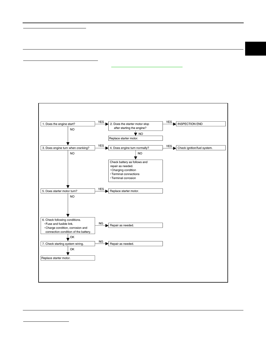
Work Flow (Without GR8-1200 NI)
INFOID:0000000008888995
OVERALL SEQUENCE
DETAILED FLOW
NOTE:
If any malfunction is found, immediately disconnect the battery cable from the negative terminal.
1.
CHECK ENGINE START
Crank the engine and check that the engine starts.
Does the engine start?
YES
>> GO TO 2.
JMBIA4454GB
Revision: 2012 September
2013 MURANO