Nissan Murano Z51 (2013 year). Manual - part 87


  Index      Manuals     Nissan Murano Z51 (2013 year) - Service and Repair Manual


Search            copyright infringement  


Content      ..     85      86      87      88     ..


Nissan Murano Z51 (2013 year). Manual - part 87


ST-100

< REMOVAL AND INSTALLATION >

[WITHOUT HEATED STEERING WHEEL]

POWER STEERING OIL PUMP

2.

Remove rear cover mounting bolts, and then remove rear cover from body assembly.

CAUTION:

• Fix oil pump with a vise if necessary.
• Use copper plates when fixing with a vise.

3.

Remove O-ring from body assembly.

4.

Remove rear side plate from cartridge, and then remove Teflon ring and O-ring from rear side plate.
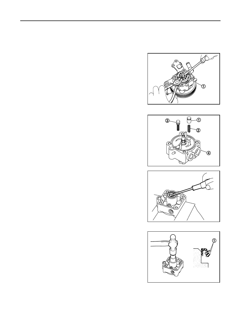
5.

Remove rotor snap ring (1) using a snap ring pliers, and remove
cam ring, rotor and vane from body assembly.

CAUTION:

When removing the snap ring, never damage the pulley
shaft.

6.

Remove front side plate.

7.

Remove cartridge, flow control valve (1), flow control valve
spring (2) and flow control valve sub assembly (3) from body
assembly (4).

CAUTION:

Never drop and damage flow control valve and flow control
valve sub assembly when removing.

8.

Remove oil seal from body assembly.

9.

Remove mounting bolt of suction pipe, and then remove suction
pipe from body assembly.

10. Remove pulley from body assembly.
11. Remove front bracket from body assembly.

12. Remove oil seal from body assembly using a flat-bladed screw-

driver.

CAUTION:

Never damage the body assembly.

ASSEMBLY

1.

Apply recommended grease to oil seal lips (1). Apply recom-
mended fluid to around oil seal. Install oil seal to body assembly
using a drift (commercial service tool).

CAUTION:

• Never reuse the oil seal.
• Fix oil pump with a vise if necessary.
• Use copper plates when fixing with a vise.

2.

Install front bracket to body assembly.

3.

Install pulley to body assembly.

4.

If dowel pin has been removed, insert it into body assembly by
hand. If it cannot be inserted by hand, lightly tap with a hammer.

JSGIA0328ZZ

JSGIA0329ZZ

JSGIA0331ZZ

JSGIA0330ZZ

Revision: 2012 September

2013 MURANO

POWER STEERING OIL PUMP

ST-101

< REMOVAL AND INSTALLATION >

[WITHOUT HEATED STEERING WHEEL]

C

D

E

F

H

I

J

K

L

M

A

B

ST

N

O

P

5.

Install flow control valve (1), flow control valve spring (2) and
flow control valve sub assembly (3) as shown in the figure to
body assembly (4).

6.

Install front side plate (3) with dowel pin (2) on flow control valve
A (1) side as shown in the figure aligning with front side plate
cutout (A) to body assembly (4).

7.

Install cam ring as shown in the figure.

8.

Install rotor so that mark faces body assembly, and then install it
to pulley shaft.

9.

Install vane to rotor so that arc of vane faces cam ring side.

10. Install rotor snap ring to slit of pulley shaft using a hammer and a

drift (commercial service tool).

CAUTION:

• Never damage rotor and pulley shaft.
• Oil pump assembly must be replaced if rotor is damaged.

JSGIA0329ZZ

SGIA1189E

SGIA0612E

SGIA0989E

SGIA0613E

Revision: 2012 September

2013 MURANO

ST-102

< REMOVAL AND INSTALLATION >

[WITHOUT HEATED STEERING WHEEL]

POWER STEERING OIL PUMP

11. Install rear side plate with dowel pin A on flow control valve A

side as shown in the figure aligning with rear side plate cutout B
to cartridge.

12. Apply recommended fluid to O-ring, and then install O-ring to

body assembly.

13. Apply recommended fluid to O-ring, and then install O-ring to

rear side plate.

14. Apply recommended fluid to Teflon ring, and then install Teflon

ring to rear side plate.

15. Install rear cover to body assembly.

16. Apply recommended fluid to O-ring, and then install O-ring to

body assembly.

17. Install suction pipe to body assembly.

18. Install rear bracket.

Inspection

INFOID:0000000008459348

RELIEF OIL PRESSURE

CAUTION:

Make sure that belt tension is normal before starting the following procedure.
1.

Connect the oil pressure gauge [SST: KV48103500 (J-26357)]
and the oil pressure gauge adapter [SST: KV48102500 (J-
33914)] between oil pump discharge connector and high-pres-
sure hose. Bleed air from the hydraulic circuit while opening
valve fully. Refer to 

ST-76, "Inspection"

.

2.

Start the engine. Run the engine until oil temperature reaches
50 to 80

°

C (122 to 176

°

F).

CAUTION:

• Leave the valve of the oil pressure gauge fully open while

starting and running the engine. If engine is started with
the valve closed, the hydraulic pressure in oil pump goes
up to the relief pressure along with unusual increase of oil
temperature.

• Be sure to keep hose clear of belts and other parts when

engine is started.

3.

Fully close the oil pressure gauge valve with engine at idle and
measure the relief oil pressure.

CAUTION:

Never keep valve closed for 10 seconds or longer.

4.

Open the valve slowly after measuring. Repair oil pump if the relief oil pressure is outside the standard.
Refer to 

ST-99, "Disassembly and Assembly"

.

5.

Disconnect the oil pressure gauge from hydraulic circuit.

PGIA0035E

Standard

Relief oil pressure

: Refer to 

ST-107, "Relief 

Oil Pressure"

.

SGIA0915E

Revision: 2012 September

2013 MURANO

POWER STEERING OIL PUMP

ST-103

< REMOVAL AND INSTALLATION >

[WITHOUT HEATED STEERING WHEEL]

C

D

E

F

H

I

J

K

L

M

A

B

ST

N

O

P

6.

When installing eye bolt (1) and copper washers (2) to oil pump
(3), refer to the figure.

CAUTION:

• Never reuse copper washer.
• Apply power steering fluid or equivalent to around copper

washer, then install eye bolt.

• Install eye bolt with eye joint (assembled to high pressure

hose) (B) protrusion (A) facing with pump side cutout, and
then tighten it to the specified torque after tightening by
hand. Refer to 

ST-104, "Exploded View"

.

• Securely insert harness connector to pressure sensor.

7.

Check fluid level, fluid leakage and air bleeding hydraulic sys-
tem after the installation. Refer to 

ST-76, "Inspection"

.

BEFORE DISASSEMBLY

Disassemble oil pump only when the following malfunctions occur.
• If oil leakage is found on oil pump.
• Oil pump pulley is damaged or deformed.
• Performance of oil pump is low. 

AFTER DISASSEMBLY

Body Assembly and Rear Cover Inspection

• Check body assembly and rear cover for internal damage. Replace rear cover if it is damaged. Replace oil

pump assembly if body assembly is damaged.

Cartridge Assembly Inspection

• Check cam ring, rotor and vane for damage. Replace cartridge assembly if necessary.

Side Plate Inspection

• Check side plate for damage. Replace side plate if necessary.

Flow Control Valve Inspection

• Check flow control valve and spring for damage. Replace if necessary.

SGIA1379E

Revision: 2012 September

2013 MURANO

ST-104

< REMOVAL AND INSTALLATION >

[WITHOUT HEATED STEERING WHEEL]

HYDRAULIC LINE

HYDRAULIC LINE

Exploded View

INFOID:0000000008459349

Removal and Installation

INFOID:0000000008459350

CAUTION:

1.

Reservoir tank bracket

2.

Bushing

3.

Reservoir tank

4.

Suction hose

5.

Clamp

6.

Copper washer

7.

High pressure piping

8.

Steering gear assembly

9.

Low pressure hose

10. Eye bolt

A.

To power steering oil pump suction 
hose.

B.

To power steering oil pump.

: Vehicle front

: Apply power steering fluid.

Refer to 

GI-4, "Components"

 for symbols not described on the above.

JSGIA0608GB

Revision: 2012 September

2013 MURANO

HYDRAULIC LINE

ST-105

< REMOVAL AND INSTALLATION >

[WITHOUT HEATED STEERING WHEEL]

C

D

E

F

H

I

J

K

L

M

A

B

ST

N

O

P

• Never apply fluid to the hose (1) and tube (2).
• Insert hose securely until it contacts spool (A) of tube.
• Leave clearance (L) when installing clamp (3).

• Install eye bolt with eye joint (assembled to high pressure

hose) (B) protrusion (A) facing with pump side cutout, and
then tighten it to the specified torque after tightening by hand.
Refer to 

ST-104, "Exploded View"

.

• Securely insert harness connector to pressure sensor.
• Apply power steering fluid to around copper washer, then

install eye bolt.

• Never reuse copper washer.

Standard

L

: 3 – 8 mm (0.12 – 0.31 in)

JSGIA0118ZZ

SGIA1379E

Revision: 2012 September

2013 MURANO

ST-106

< SERVICE DATA AND SPECIFICATIONS (SDS) 

[WITHOUT HEATED STEERING WHEEL]

SERVICE DATA AND SPECIFICATIONS (SDS)

SERVICE DATA AND SPECIFICATIONS (SDS)

SERVICE DATA AND SPECIFICATIONS (SDS)

General Specifications

INFOID:0000000008459351

Steering Wheel Axial End Play and Play

INFOID:0000000008459352

Unit: mm (in)

Steering Wheel Turning Force

INFOID:0000000008459353

Unit: N·m (kg-m, in-lb)

Steering Angle

INFOID:0000000008459354

Unit: Degree minute (Decimal degree)

Steering Column Length

INFOID:0000000008459355

Unit: mm (in)

Steering Column Mounting Dimensions

INFOID:0000000008459356

Unit: mm (in)

Steering Column Operating Range

INFOID:0000000008459357

Steering gear model

PR26AF

Fluid capacity (Approx.)

 (US qt, lmp qt)

1.0 (1-1/8, 7/8)

Item

Standard

Steering wheel axial end play

0 (0)

Steering wheel play on the outer circumference

0 – 35 (0 – 1.38)

Item

Standard

Steering wheel turning force

7.45 (0.76, 66)

Item

Standard

Wheel size: 18 inch

Wheel size: 20 inch

Inner wheel

Minimum

33

°

30

 (33.5

°

)

32

°

00

 (32.0

°

)

Nominal

36

°

30

 (36.5

°

)

35

°

00

 (35.0

°

)

Maximum

37

°

30

 (37.5

°

)

36

°′

 (36.0

°

)

Outer wheel

Nominal

31

°

30

 (31.5

°

)

30

°

30

 (30.5

°

)

Item

Standard

Steering column length

463 (18.23)

Item

Standard

Mounting dimension

30 (1.18) or less

Item

Standard

Tilt operating range 

15

°

Telescopic operating range 

40 mm (1.57 in)

Rotating torque

0.49 N·m (0.05 kg-m, 4 in-lb)

Revision: 2012 September

2013 MURANO

SERVICE DATA AND SPECIFICATIONS (SDS)

ST-107

< SERVICE DATA AND SPECIFICATIONS (SDS) 

[WITHOUT HEATED STEERING WHEEL]

C

D

E

F

H

I

J

K

L

M

A

B

ST

N

O

P

Lower Shaft Length

INFOID:0000000008459358

Unit: mm (in)

Rack Sliding Force

INFOID:0000000008459359

Unit: N (kg, lb)

Rack Stroke

INFOID:0000000008459360

Unit: mm (in)

Socket Swing Force and Rotating Torque

INFOID:0000000008459361

SWING FORCE

Unit: N (kg, lb)

ROTATING TORQUE

Unit: N·m (kg-m, in-lb)

Socket Axial End Play

INFOID:0000000008459362

Unit: mm (in)

Inner Socket Length

INFOID:0000000008459363

Unit: mm (in)

Relief Oil Pressure

INFOID:0000000008459364

Unit: kPa (kg/cm

2

, psi)

Item

Standard

Lower shaft length (extended position)

524.6 – 525.6 (20.65 – 20.69)

Item

Standard

2WD

AWD

Rack sliding force

195 – 258 (19.9 – 26.3, 43.8 – 

57.9)

227 – 305 (23.2 – 31.1, 51.1 – 

68.5)

Item

Standard

Wheel size: 18 inch

Wheel size: 20 inch

Rack stroke neutral position

70.5 (2.776)

68.0 (2.677)

Item

Standard

Outer socket

4.81 – 45.7 (0.5 – 4.6, 1.1 – 10.2)

Inner socket

8.9 – 64 (0.91 – 6.5, 2.01 – 14.3)

Item

Standard

Outer socket 

0.3 – 2.9 (0.03 – 0.29, 3 – 25)

Item

Standard

Outer socket

0.5 (0.02) or less

Inner socket

0.2 (0.008) or less

Item

Standard

Inner socket length

120.6 (4.75)

Item

Standard

Relief oil pressure

9,400 – 10,400 (95.9 – 106.1, 1,363 – 1,508)

Revision: 2012 September

2013 MURANO

STC-1

STEERING

C

D

E

F

H

I

J

K

L

M

SECTION 

STC

A

B

STC

N

O

P

CONTENTS

STEERING CONTROL SYSTEM

BASIC INSPECTION  ....................................

2

DIAGNOSIS AND REPAIR WORK FLOW  .........

2

Work Flow  .................................................................

2

SYSTEM DESCRIPTION  ..............................

3

EPS SYSTEM  ......................................................

3

System Diagram ........................................................

3

System Description  ...................................................

3

Component Parts Location ........................................

5

Component Description .............................................

5

DTC/CIRCUIT DIAGNOSIS  ..........................

6

POWER SUPPLY AND GROUND CIRCUIT .......

6

Description ................................................................

6

Diagnosis Procedure .................................................

6

POWER STEERING SOLENOID VALVE  ...........

7

Description ................................................................

7

Diagnosis Procedure .................................................

7

Component Inspection  ..............................................

8

ENGINE SPEED SIGNAL CIRCUIT  ....................

9

Description ................................................................

9

Diagnosis Procedure .................................................

9

VEHICLE SPEED SIGNAL CIRCUIT  .................

11

Description ..............................................................

11

Diagnosis Procedure ...............................................

11

ECU DIAGNOSIS INFORMATION ..............

13

POWER STEERING CONTROL UNIT ..............

13

Reference Value ......................................................

13

Wiring Diagram - ELECTRONICALLY CON-
TROLLED POWER STEERING SYSTEM -  ............

15

Fail-Safe ..................................................................

15

SYMPTOM DIAGNOSIS  ..............................

17

UNBALANCE STEERING WHEEL TURNING 
FORCE (TORQUE VARIATION) .......................

17

Description ...............................................................

17

Diagnosis Procedure  ...............................................

17

PRECAUTION ..............................................

18

PRECAUTIONS .................................................

18

FOR USA AND CANADA  ..........................................

18

FOR USA AND CANADA : Precaution for Supple-
mental Restraint System (SRS) "AIR BAG" and 
"SEAT BELT PRE-TENSIONER" ............................

18

FOR MEXICO .............................................................

18

FOR MEXICO : Precaution for Supplemental Re-
straint System (SRS) "AIR BAG" and "SEAT BELT 
PRE-TENSIONER" ..................................................

18

REMOVAL AND INSTALLATION  ...............

20

POWER STEERING CONTROL UNIT ..............

20

Removal and Installation  .........................................

20

Revision: 2012 September

2013 MURANO

STC-2

< BASIC INSPECTION >

DIAGNOSIS AND REPAIR WORK FLOW

BASIC INSPECTION

DIAGNOSIS AND REPAIR WORK FLOW

Work Flow

INFOID:0000000008455025

DETAILED FLOW

1.

COLLECT THE INFORMATION FROM THE CUSTOMER

It is also important to clarify customer complaints before inspection. First of all, reproduce symptoms and
understand them fully. Ask customer about his/her complaints carefully. In some cases, it is necessary to
check symptoms by driving vehicle with customer.

CAUTION:

Customers are not professional. It is dangerous to make an easy guess like “maybe the customer
means that...,” or “maybe the customer mentions this symptom”.

>> GO TO 2.

2.

CHECK THE STATUS

1.

Power steering fluid leakage and check the power steering fluid level. Refer to 

ST-31, "Inspection"

.

2.

Check the drive belt tension. Refer to 

EM-16, "Checking"

.

3.

Check the power steering gear for damages, cracks and fluid leakage. Refer to 

ST-54, "Inspection"

.

4.

Check the relief oil pressure. Refer to 

ST-60, "Inspection"

 (With heated steering wheel), 

ST-102, "Inspec-

tion"

 (Without heated steering wheel).

>> GO TO 3.

3.

DIAGNOSIS CHART BY SYMPTOM

Perform the diagnosis by symptom. Refer to 

STC-17, "Diagnosis Procedure"

.

>> GO TO 4.

4.

FINAL CHECK

Check the input/output standard values for the power steering control unit.

Are the power steering control unit input/output values within standard ranges respectively?

YES

>> INSPECTION END

NO

>> GO TO 2.

Revision: 2012 September

2013 MURANO

EPS SYSTEM

STC-3

< SYSTEM DESCRIPTION >

C

D

E

F

H

I

J

K

L

M

A

B

STC

N

O

P

SYSTEM DESCRIPTION

EPS SYSTEM

System Diagram

INFOID:0000000008455026

CONTROL DIAGRAM

CROSS-SECTIONAL VIEW

System Description

INFOID:0000000008455027

• The EPS system controls the power steering solenoid valve through the power steering control unit.

JSGIA0119GB

1.

Combination meter

2.

Power steering control unit

3.

Power steering solenoid valve

4.

Steering gear assembly

5.

Gear housing assembly

6.

Gear sub-assembly

7.

Pinion

8.

Power steering oil pump

9.

Reservoir tank

JSGIA0376ZZ

Revision: 2012 September

2013 MURANO

STC-4

< SYSTEM DESCRIPTION >

EPS SYSTEM

• The valve driving voltage to control the power steering solenoid

valve varies according to the vehicle speed.

OPERATION PRINCIPLE

During Parking (When Turning The Steering Wheel To The Right.)

1.

Power steering solenoid valve is closed while a vehicle is stopped.

2.

Pinion “1R”, “2R” and “3R” are closed depending on steering torque of steering wheel.

3.

Oil pressure “P” in the gear housing assembly is the sum of oil pressures occurred in “2R” and “3R”. This
results in a light steering force because of high pressure.

During High-speed Operation

1.

Power steering solenoid valve is opened during high-speed operation.

2.

Pinion “1R”, “2R” and “3R” are closed depending on steering torque of steering wheel.

3.

Oil pressure “2R” does not occur because the power steering solenoid valve is on full throttle.

4.

Oil pressure “P” in the gear housing assembly includes only oil pressure occurred in “3R” and results in a
heavy steering force.

JSGIA0374GB

JSGIA0020GB

JSGIA0021GB

Revision: 2012 September

2013 MURANO

EPS SYSTEM

STC-5

< SYSTEM DESCRIPTION >

C

D

E

F

H

I

J

K

L

M

A

B

STC

N

O

P

Component Parts Location

INFOID:0000000008455028

Component Description

INFOID:0000000008455029

1.

Power steering solenoid valve

2.

Power steering control unit

A.

Steering gear assembly

B.

Glove box assembly removed

: Vehicle front

JSGIA0301ZZ

Component parts

Reference/Function

Power steering control unit

• Signals from various sensors control the driving voltage to the power steering solenoid valve.
• The power steering control unit controls the driving voltage to the power steering solenoid valve 

for maintaining the power steering assist force when the fail-safe function is activated. (The en-
gine speed signals control EPS system if any vehicle speed signal error is detected.)

Combination meter

STC-11, "Description"

ECM

STC-9, "Description"

Power steering solenoid valve

STC-7, "Description"

Revision: 2012 September

2013 MURANO

STC-6

< DTC/CIRCUIT DIAGNOSIS >

POWER SUPPLY AND GROUND CIRCUIT

DTC/CIRCUIT DIAGNOSIS

POWER SUPPLY AND GROUND CIRCUIT

Description

INFOID:0000000008455030

Power supply to EPS system

Diagnosis Procedure

INFOID:0000000008455031

1.

CHECK POWER SUPPLY

1.

Turn the ignition switch OFF.

2.

Disconnect power steering control unit harness connector.

3.

Check voltage between power steering control unit harness connector and ground.

4.

Turn the ignition switch ON.

CAUTION:

Never start the engine.

5.

Check voltage between power steering control unit harness connector and ground.

Is the inspection result normal?

YES

>> GO TO 2.

NO

>>

Check the following. If any items are damaged, repair or replace damaged parts.

• 10A fuses (#3) open
- Harness for short or open between ignition switch and power steering control unit harness con-

nector No. 3 terminal.

- Ignition switch. Refer to 

PCS-65, "Component Inspection"

.

2.

CHECK GROUND CIRCUIT

1.

Turn the ignition switch OFF.

2.

Check continuity between power steering control unit harness connector and ground.

Is the inspection result normal?

YES

>> GO TO 3.

NO

>> Repair open circuit or short to power in harness or connectors.

3.

CHECK TERMINALS AND HARNESS CONNECTORS

Check power steering control unit pin terminals for damage or loose connection with harness connector.

Is the inspection result normal?

YES

>> INSPECTION END

NO

>> Repair or replace damaged parts.

Power steering control unit

Voltage

(Approx.)

Connector

Terminal

M61

3 Ground

V

Power steering control unit

Voltage

(Approx.)

Connector

Terminal

M61

3 Ground

Battery 

voltage

Power steering control unit

Continuity

Connector

Terminal

M61

6 Ground

Existed

Revision: 2012 September

2013 MURANO

POWER STEERING SOLENOID VALVE

STC-7

< DTC/CIRCUIT DIAGNOSIS >

C

D

E

F

H

I

J

K

L

M

A

B

STC

N

O

P

POWER STEERING SOLENOID VALVE

Description

INFOID:0000000008455032

Power steering solenoid valve controls the power steering oil pressure in the gear housing assembly.

Diagnosis Procedure

INFOID:0000000008455033

1.

CHECK POWER STEERING SOLENOID VALVE SIGNAL

Check voltage between power steering control unit harness connector and ground.

Is the inspection result normal?

YES

>> GO TO 4.

NO

>> GO TO 2.

2.

CHECK HARNESS BETWEEN POWER STEERING SOLENOID VALVE AND POWER STEERING CON-

TROL UNIT

1.

Turn the ignition switch OFF.

2.

Disconnect power steering solenoid valve harness connector.

3.

Disconnect power steering control unit harness connector.

4.

Check the continuity between power steering solenoid valve harness connector and the power steering
control unit harness connector.

5.

Check continuity between power steering control unit harness connector and ground.

Is the inspection result normal?

 YES

>> GO TO 3.

 NO

>> Repair or replace damaged parts.

3.

CHECK POWER STEERING SOLENOID VALVE

Check power steering solenoid valve. Refer to 

STC-8, "Component Inspection"

.

Is the inspection result normal?

 YES

>> GO TO 4.

 NO

>> Replace gear-sub assembly. Refer to 

ST-44, "Exploded View"

 (With heated steering wheel), 

ST-

86, "Exploded View"

 (Without heated steering wheel).

4.

CHECK TERMINALS AND HARNESS CONNECTORS

• Check power steering control unit pin terminals for damage or loose connection with harness connector.
• Check power steering solenoid valve pin terminals for damage or loose connection with harness connector.

Is the inspection result normal?

Power steering control unit

Condition

Voltage

(Approx.)

Connector

Terminal

M61

 1 

Ground

Vehicle speed: 0 km/h (0 MPH)
(Engine is running)

4.4 – 6.6 V

Vehicle speed: 100 km/h (62 MPH)

2.4 – 3.6 V

Power steering solenoid valve

Power steering control unit

Continuity

Connector

Terminal

Connector

Terminal

E52

1

M61

1

Existed

E52

2

M61

5

Existed

Power steering control unit

Continuity

Connector

Terminal

M61

1

Ground

Not existed

M61

5

Revision: 2012 September

2013 MURANO

STC-8

< DTC/CIRCUIT DIAGNOSIS >

POWER STEERING SOLENOID VALVE

YES

>> INSPECTION END

NO

>> Repair or replace damaged parts.

Component Inspection

INFOID:0000000008455034

1.

CHECK POWER STEERING SOLENOID VALVE

1.

Turn the ignition switch OFF.

2.

Disconnect power steering solenoid valve harness connector.

3.

Check resistance between power steering solenoid valve connector terminals.

4.

Check power steering solenoid valve by listening for its operation sound while applying battery voltage to
power steering solenoid valve connector E52 terminals 1 (positive) and 2 (negative).

Is the inspection result normal?

 YES

>> INSPECTION END

 NO

>> Replace gear-sub assembly. Refer to 

ST-44, "Exploded View"

 (With heated steering wheel), 

ST-

86, "Exploded View"

 (Without heated steering wheel).

Power steering solenoid valve

Resistance (Approx.)

Terminal

1 2

– 

Ω

Revision: 2012 September

2013 MURANO


Content      ..     85      86      87      88     ..