Nissan Murano Z51 (2012 year). Manual - part 29
FRONT DRIVE SHAFT
FAX-43
< REMOVAL AND INSTALLATION >
[AWD]
C
E
F
G
H
I
J
K
L
M
A
B
FAX
N
O
P
FRONT DRIVE SHAFT
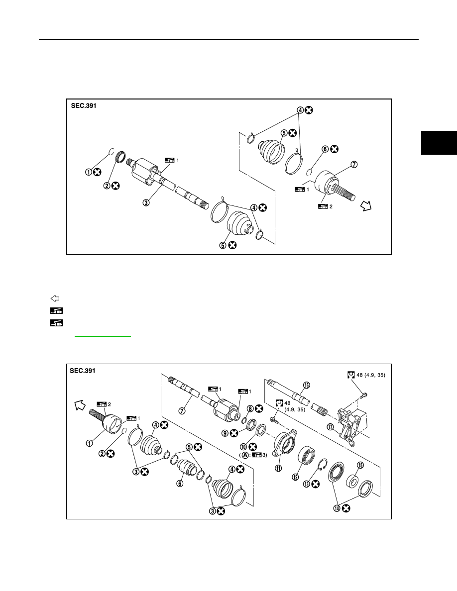
Exploded View
INFOID:0000000007541227
LEFT SIDE
RIGHT SIDE
1.
Circular clip
2.
Dust shield
3.
Housing assembly
4.
Boot band
5.
Boot
6.
Circular clip
7.
Joint sub-assembly
: Wheel side
1: Fill NISSAN Genuine grease or equivalent.
2: Apply paste [service parts (440037S000)].
Refer to
for symbols not described on the above.
JPDIF0243ZZ
1.
Joint sub-assembly
2.
Circular clip
3.
Boot band
4.
Boot
5.
Damper band
6.
Dynamic damper
7.
Housing assembly
8.
Circular clip
9.
Dust shield
10. Oil seal
11.
Bearing housing
12. Bearing bracket
JPDIF0241GB
Revision: 2013 February
2012 MURANO