Nissan Murano Z51 (2011 year). Manual - part 16
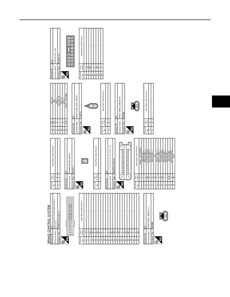
ABS ACTUATOR AND ELECTRIC UNIT (CONTROL UNIT)
BRC-103
< ECU DIAGNOSIS INFORMATION >
[VDC/TCS/ABS]
C
D
E
G
H
I
J
K
L
M
A
B
BRC
N
O
P
JCFWM0719GB
Revision: 2011 November
2011 MURANO
|
|
|
ABS ACTUATOR AND ELECTRIC UNIT (CONTROL UNIT) BRC-103 < ECU DIAGNOSIS INFORMATION > [VDC/TCS/ABS] C D E G H I J K L M A B BRC N O P JCFWM0719GB Revision: 2011 November 2011 MURANO |