Nissan Murano Z51 (2011 year). Manual - part 17


  Index      Manuals     Nissan Murano Z51 (2011 year) - Service and Repair Manual


Search            copyright infringement  


Content      ..     15      16      17      18     ..


Nissan Murano Z51 (2011 year). Manual - part 17


WHEEL SENSOR

BRC-119

< REMOVAL AND INSTALLATION >

[VDC/TCS/ABS]

C

D

E

G

H

I

J

K

L

M

A

B

BRC

N

O

P

REMOVAL AND INSTALLATION

WHEEL SENSOR

FRONT WHEEL SENSOR

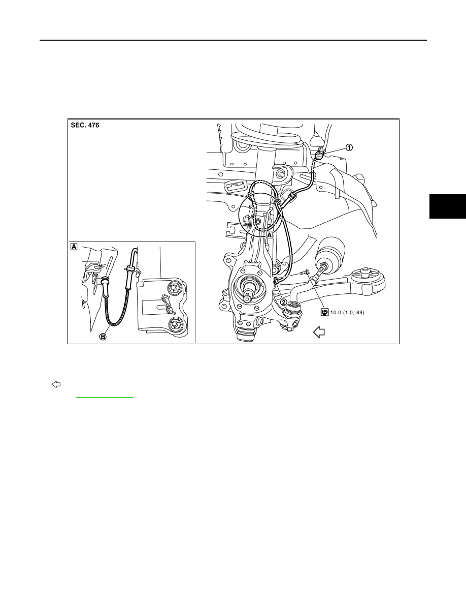
FRONT WHEEL SENSOR : Exploded View

INFOID:0000000006263544

NOTE:
The above figure (front side) shows left side. Right side is the mirror image.

FRONT WHEEL SENSOR : Removal and Installation

INFOID:0000000006263545

REMOVAL

Be careful with the following when removing sensor.

CAUTION:

• Never twist sensor harness as much as possible, when removing it. Pull sensors out without pulling

sensor harness.

• Be careful to avoid damaging sensor edges or rotor teeth. Remove wheel sensor first before remov-

ing front or rear wheel hub. This is to avoid damage to sensor wiring and loss of sensor function.

• When you see the harness of the wheel sensor from the front side of the vehicle ensure that the

white lines (B) are not twisted.

INSTALLATION

Be careful with the following when installing wheel sensor. Tighten installation bolts to the specified torques.
• When installing, make sure there is no foreign material such as iron chips on and in the mounting hole of the

wheel sensor. Make sure no foreign material has been caught in the sensor rotor. Remove any foreign mate-
rial and clean the mount.

1.

Front LH wheel sensor connector

2.

Front LH wheel sensor

B.

White line (slant line)

: Vehicle front

Refer to 

GI-4, "Components"

 for symbol in the figure.

JSFIA0190GB

Revision: 2011 November

2011 MURANO

BRC-120

< REMOVAL AND INSTALLATION >

[VDC/TCS/ABS]

WHEEL SENSOR

• When installing wheel sensor, be sure to press rubber grommets in until they lock at locations shown above

in the figure. When installed, harness must not be twisted.

REAR WHEEL SENSOR

REAR WHEEL SENSOR : Exploded View

INFOID:0000000006263546

REAR WHEEL SENSOR : Removal and Installation

INFOID:0000000006263547

REMOVAL

Be careful with the following when removing sensor.

CAUTION:

• Never twist sensor harness as much as possible, when removing it. Pull sensors out without pulling

sensor harness.

• Be careful to avoid damaging sensor edges or rotor teeth. Remove wheel sensor first before remov-

ing front or rear wheel hub. This is to avoid damage to sensor wiring and loss of sensor function.

INSTALLATION

Be careful with the following when installing wheel sensor. Tighten installation bolts to the specified torques.
• When installing, make sure there is no foreign material such as iron chips on and in the mounting hole of the

wheel sensor. Make sure no foreign material has been caught in the sensor rotor. Remove any foreign mate-
rial and clean the mount.

• When installing wheel sensor, be sure to press rubber grommets in until they lock at locations shown above

in the figure. When installed, harness must not be twisted.

1.

Rear RH wheel sensor

2.

Rear RH wheel sensor connector

3.

Rear LH wheel sensor connector

4.

Rear LH wheel sensor

B.

AWD models only

C.

White line (slant line)

: Vehicle front

Refer to 

GI-4, "Components"

 for symbol in the figure.

JSFIA0191GB

Revision: 2011 November

2011 MURANO

SENSOR ROTOR

BRC-121

< REMOVAL AND INSTALLATION >

[VDC/TCS/ABS]

C

D

E

G

H

I

J

K

L

M

A

B

BRC

N

O

P

SENSOR ROTOR

FRONT SENSOR ROTOR

FRONT SENSOR ROTOR : Exploded View

INFOID:0000000006263548

Refer to 

FAX-10, "Exploded View"

 (2WD models), 

FAX-36, "Exploded View"

 (AWD models).

FRONT SENSOR ROTOR : Removal and Installation

INFOID:0000000006263549

REMOVAL

Sensor rotor cannot be disassembled. Remove the sensor rotor together with hub bearing assembly. Refer to

FAX-10, "Removal and Installation"

 (2WD models), 

FAX-36, "Removal and Installation"

 (AWD models).

INSTALLATION

Sensor rotor cannot be disassembled. Install the sensor rotor together with hub bearing assembly. Refer to

FAX-10, "Removal and Installation"

 (2WD models), 

FAX-36, "Removal and Installation"

 (AWD models). 

REAR SENSOR ROTOR

REAR SENSOR ROTOR : Exploded View

INFOID:0000000006263550

Refer to 

RAX-5, "Exploded View"

 (2WD models), 

RAX-13, "Exploded View"

 (AWD models).

REAR SENSOR ROTOR : Removal and Installation

INFOID:0000000006263551

REMOVAL

Sensor rotor cannot be disassembled. Remove the sensor rotor together with hub bearing assembly. Refer to

RAX-5, "Removal and Installation"

 (2WD models), 

RAX-15, "Removal and Installation"

 (AWD models).

INSTALLATION

Sensor rotor cannot be disassembled. Install the sensor rotor together with hub bearing assembly. Refer to

RAX-5, "Removal and Installation"

 (2WD models), 

RAX-15, "Removal and Installation"

 (AWD models).

Revision: 2011 November

2011 MURANO

BRC-122

< REMOVAL AND INSTALLATION >

[VDC/TCS/ABS]

ABS ACTUATOR AND ELECTRIC UNIT (CONTROL UNIT)

ABS ACTUATOR AND ELECTRIC UNIT (CONTROL UNIT)

Exploded View

INFOID:0000000006263552

Removal and Installation

INFOID:0000000006263553

REMOVAL

CAUTION:

• Before servicing, disconnect the battery cable from negative terminal.
• To remove brake tube, use a flare nut wrench to prevent flare nuts and brake tube from being dam-

aged. To install, use flare nut crowfoot and torque wrench.

• Never apply excessive impact to ABS actuator and electric unit (control unit), such as dropping it.
• Never remove and install actuator by holding harness.
1.

Remove cowl top. Refer to 

EXT-20, "Exploded View"

.

2.

Disconnect ABS actuator and electric unit (control unit) connector.

3.

Loosen brake tube flare nuts, then remove brake tubes from ABS actuator and electric unit (control unit).

4.

Remove ABS actuator and electric unit (control unit) bracket mounting nut.

5.

Remove ABS actuator and electric unit (control unit) from vehicle.

INSTALLATION

Note the following, and install in the reverse order of removal.

CAUTION:

• Before servicing, disconnect the battery cable from negative terminal.

1.

ABS actuator and electric unit (control 
unit)

2.

Bracket

A.

To rear RH brake caliper

B.

To rear LH brake caliper

C.

From master cylinder primary side

D.

To front RH brake caliper

E.

To front LH brake caliper

F.

From master cylinder secondary side

: Vehicle front

Refer to 

GI-4, "Components"

 for symbol in the figure.

JSFIA0192GB

Revision: 2011 November

2011 MURANO

ABS ACTUATOR AND ELECTRIC UNIT (CONTROL UNIT)

BRC-123

< REMOVAL AND INSTALLATION >

[VDC/TCS/ABS]

C

D

E

G

H

I

J

K

L

M

A

B

BRC

N

O

P

• To remove brake tube, use a flare nut wrench to prevent flare nuts and brake tube from being dam-

aged. To install, use flare nut crowfoot and torque wrench.

• Never apply excessive impact to ABS actuator and electric unit (control unit), such as dropping it.
• Never remove and install actuator by holding harness.
• After work is completed, bleed air from brake tube. Refer to 

BR-12, "Bleeding Brake System"

.

• After installing harness connector in the ABS actuator and electric unit (control unit), make sure

connector is securely locked. 

• After removing/replacing an ABS actuator and electric unit (control unit), be sure to perform the fol-

lowing procedure.

- Adjustment of steering angle sensor neutral position: Refer to 

BRC-9, "ADJUSTMENT OF STEERING

ANGLE SENSOR NEUTRAL POSITION : Description"

.

- Calibration of decel G sensor: Refer to 

BRC-10, "CALIBRATION OF DECEL G SENSOR : Descrip-

tion"

.

Install ABS actuator and electric unit (control unit) as per the following steps.

1.

Temporarily tighten mounting bolt (1) because the bracket (2) is
temporarily being hold.

2.

Tighten mounting bolt (3) while holding the bracket.

3.

Tighten mounting bolts to the specified torque in the order of (4),
(1).

JSFIA0400ZZ

Revision: 2011 November

2011 MURANO

BRC-124

< REMOVAL AND INSTALLATION >

[VDC/TCS/ABS]

YAW RATE/SIDE/DECEL G SENSOR

YAW RATE/SIDE/DECEL G SENSOR

Exploded View

INFOID:0000000006263554

Removal and Installation

INFOID:0000000006263555

REMOVAL

CAUTION:

Never drop or strike yaw rate/side/decel G sensor, or never use power tool etc., because yaw rate/side/
decel G sensor is sensitive to the impact.

1.

Remove center console assembly. Refer to 

IP-20, "Exploded View"

.

2.

Disconnect yaw rate/side/decel G sensor harness connector.

3.

Remove mounting nuts.

4.

Remove yaw rate/side/decel G sensor.

INSTALLATION

Note the following, and install in the reverse order of removal.

CAUTION:

• Never drop or strike yaw rate/side/decel G sensor, or never use power tool etc., because yaw rate/

side/decel G sensor is sensitive to the impact.

• After work, make sure to calibration of decel G sensor. Refer to 

BRC-10, "CALIBRATION OF DECEL

G SENSOR : Description"

.

1.

Yaw rate/side/decel G sensor

2.

Connector

: Vehicle front

Refer to 

GI-4, "Components"

 for symbol in the figure.

JPFIC0113GB

Revision: 2011 November

2011 MURANO

STEERING ANGLE SENSOR

BRC-125

< REMOVAL AND INSTALLATION >

[VDC/TCS/ABS]

C

D

E

G

H

I

J

K

L

M

A

B

BRC

N

O

P

STEERING ANGLE SENSOR

Exploded View

INFOID:0000000006263556

Removal and Installation

INFOID:0000000006263557

REMOVAL

1.

Remove spiral cable assembly. Refer to 

SR-14, "Exploded View"

.

2.

Remove steering angle sensor from spiral cable assembly.

INSTALLATION

Note the following, and install in the reverse order of removal.

CAUTION:

• Never reuse steering angle sensor.
• After work, make sure to adjust neutral position of steering angle sensor. Refer to 

BRC-9, "ADJUST-

MENT OF STEERING ANGLE SENSOR NEUTRAL POSITION : Description"

.

1.

Steering angle sensor

: Vehicle front

JPFIC0056ZZ

Revision: 2011 November

2011 MURANO

CCS-2

< SYSTEM DESCRIPTION >

[ASCD]

AUTOMATIC SPEED CONTROL DEVICE (ASCD)

SYSTEM DESCRIPTION

AUTOMATIC SPEED CONTROL DEVICE (ASCD)

Information

INFOID:0000000006854194

Automatic Speed Control Device (ASCD) system is controlled by ECM.
Regarding the information for ASCD system, refer to 

EC-66, "System Description"

.

Revision: 2011 November

2011 MURANO

CHG

CHG-1

ELECTRICAL & POWER CONTROL

C

D

E

F

G

H

I

J

K

L

B

SECTION 

CHG

A

O

P

N

CONTENTS

CHARGING SYSTEM

BASIC INSPECTION  ....................................

3

DIAGNOSIS AND REPAIR WORKFLOW  ..........

3

Work Flow  .................................................................

3

SYSTEM DESCRIPTION  ..............................

6

CHARGING SYSTEM ..........................................

6

System Diagram ........................................................

6

System Description  ...................................................

6

Component Parts Location ........................................

6

Component Description ............................................

6

POWER GENERATION VOLTAGE VARI-
ABLE CONTROL SYSTEM .................................

8

System Diagram ........................................................

8

System Description  ...................................................

8

Component Parts Location ........................................

8

Component Description .............................................

9

DTC/CIRCUIT DIAGNOSIS  .........................

10

B TERMINAL CIRCUIT  ......................................

10

Description ..............................................................

10

Diagnosis Procedure ...............................................

10

L TERMINAL CIRCUIT (OPEN)  .........................

11

Description ..............................................................

11

Diagnosis Procedure ...............................................

11

L TERMINAL CIRCUIT (SHORT) .......................

13

Description ..............................................................

13

Diagnosis Procedure ...............................................

13

S TERMINAL CIRCUIT  ......................................

14

Description ..............................................................

14

Diagnosis Procedure ...............................................

14

CHARGING SYSTEM .........................................

15

Wiring Diagram - CHARGING SYSTEM -  ...............

15

SYMPTOM DIAGNOSIS  ..............................

20

CHARGING SYSTEM  .......................................

20

Symptom Table  .......................................................

20

PRECAUTION ..............................................

21

PRECAUTIONS .................................................

21

FOR USA AND CANADA  ..........................................

21

FOR USA AND CANADA : Precaution for Supple-
mental Restraint System (SRS) "AIR BAG" and 
"SEAT BELT PRE-TENSIONER" ............................

21

FOR USA AND CANADA : Precaution for Power 
Generation Voltage Variable Control System ..........

21

FOR MEXICO .............................................................

21

FOR MEXICO : Precaution for Supplemental Re-
straint System (SRS) "AIR BAG" and "SEAT BELT 
PRE-TENSIONER" ..................................................

21

FOR MEXICO : Precaution for Power Generation 
Voltage Variable Control System .............................

22

PREPARATION ...........................................

23

PREPARATION .................................................

23

Special Service Tools  ..............................................

23

Commercial Service Tools .......................................

23

PERIODIC MAINTENANCE  ........................

24

CHARGING SYSTEM PRELIMINARY IN-
SPECTION ........................................................

24

Inspection Procedure ...............................................

24

POWER GENERATION VOLTAGE VARI-
ABLE CONTROL SYSTEM OPERATION IN-
SPECTION ........................................................

25

Inspection Procedure ...............................................

25

REMOVAL AND INSTALLATION  ...............

27

ALTERNATOR ..................................................

27

Exploded View .........................................................

27

Removal and Installation  .........................................

28

Revision: 2011 November

2011 MURANO

CHG

DIAGNOSIS AND REPAIR WORKFLOW

CHG-3

< BASIC INSPECTION >

C

D

E

F

G

H

I

J

K

L

B

A

O

P

N

BASIC INSPECTION

DIAGNOSIS AND REPAIR WORKFLOW

Work Flow

INFOID:0000000006260538

OVERALL SEQUENCE

DETAILED FLOW

JSMIA0009GB

Revision: 2011 November

2011 MURANO

CHG-4

< BASIC INSPECTION >

DIAGNOSIS AND REPAIR WORKFLOW

NOTE:
To ensure a complete and thorough diagnosis, the battery, starter and alternator test segments must be done
as a set from start to finish.

1.

PRELIMINARY INSPECTION

Perform the preliminary inspection. Refer to 

CHG-24, "Inspection Procedure"

.

>> GO TO 2.

2.

STOP POWER GENERATION VOLTAGE VARIABLE CONTROL SYSTEM

Stop the operation of the power generation voltage variable control in either of the following procedures.
• After selecting “ENGINE” of “SELECT SYSTEM” using CONSULT-III, set the DUTY value of “ALTERNATOR

DUTY” to 0 % by selecting “ALTERNATOR DUTY” of “Active Test”. Continue “Active Test” until the end of
inspection. (When the DUTY value is 0 or 100 %, the normal power generation is performed according to the
characteristic of the IC voltage regulator of the alternator.)

• Turn the ignition switch OFF, and disconnect the battery current sensor connector. [However, DTC (P1550 -

P1554) of the engine might remain. After finishing the inspection, connect the battery current sensor connec-
tor and erase the self-diagnostic results history of the engine using CONSULT-III.]

>> GO TO 3.

3.

DIAGNOSIS WITH STARTING/CHARGING SYSTEM TESTER

Perform the charging system test using Starting/Charging System Tester (SST: J-44373). For details and oper-
ating instructions, refer to Technical Service Bulletin.

Test result

CHARGING SYSTEM NORMAL>>Charging system is normal and will also show “DIODE RIPPLE” test

result.

NO CHARGING VOLTAGE>>GO TO 4.
LOW CHARGING VOLTAGE>>GO TO 12.
HIGH CHARGING VOLTAGE>>GO TO 14.
DIODE RIPPLE NORMAL>>Diode ripple is OK and will also show “CHARGING VOLTAGE” test result.
EXCESS RIPPLE DETECTED>>Replace the alternator. Perform “DIODE RIPPLE” test again using Starting/

Charging System Tester (SST: J-44373) to confirm repair.

DIODE RIPPLE NOT DETECTED>>GO TO 4.

4.

INSPECTION WITH CHARGE WARNING LAMP (IGNITION SWITCH IS ON)

Turn the ignition switch ON.

Does the charge warning lamp illuminate?

YES

>> GO TO 6.

NO

>> GO TO 5.

5.

“L” TERMINAL CIRCUIT (OPEN) INSPECTION

Check “L” terminal circuit (open). Refer to 

CHG-11, "Diagnosis Procedure"

.

Is the “L” terminal circuit normal?

YES

>> Replace alternator.

NO

>> Repair as needed.

6.

INSPECTION WITH CHARGE WARNING LAMP (IDLING)

Start the engine and run it at idle.

Does the charge warning lamp turn OFF?

YES

>> GO TO 9.

NO

>> GO TO 7.

7.

“L” TERMINAL CIRCUIT (SHORT) INSPECTION

Check “L” terminal circuit (short). Refer to 

CHG-13, "Diagnosis Procedure"

.

Is the “L” terminal circuit normal?

YES

>> GO TO 8.

NO

>> Repair as needed.

Revision: 2011 November

2011 MURANO

CHG

DIAGNOSIS AND REPAIR WORKFLOW

CHG-5

< BASIC INSPECTION >

C

D

E

F

G

H

I

J

K

L

B

A

O

P

N

8.

“S” TERMINAL CIRCUIT INSPECTION

Check “S” terminal circuit. Refer to 

CHG-14, "Diagnosis Procedure"

.

Is the “S” terminal circuit normal?

YES

>> GO TO 10.

NO

>> Repair as needed.

9.

INSPECTION WITH CHARGE WARNING LAMP (ENGINE AT 3,000 RPM)

Increase and maintain the engine speed at 3,000 rpm.

Does the charge warning lamp remain off?

YES

>> GO TO 11.

NO

>> GO TO 10.

10.

INSPECTION OF ALTERNATOR PULLEY

Check alternator pulley. Refer to 

CHG-29, "Inspection"

.

Is alternator pulley normal?

YES

>> Replace alternator.

NO

>> Repair as needed.

11.

“B” TERMINAL CIRCUIT INSPECTION

Check “B” terminal circuit. Refer to 

CHG-10, "Diagnosis Procedure"

.

Is “B” terminal circuit normal?

YES

>> Replace alternator.

NO

>> Repair as needed.

12.

“B” TERMINAL CIRCUIT INSPECTION

Check “B” terminal circuit. Refer to 

CHG-10, "Diagnosis Procedure"

.

Is “B” terminal circuit normal?

YES

>> GO TO 13.

NO

>> Repair as needed.

13.

INSPECTION OF ALTERNATOR PULLEY

Check alternator pulley. Refer to 

CHG-29, "Inspection"

.

Is alternator pulley normal?

YES

>> Replace alternator.

NO

>> Repair as needed.

14.

“S” TERMINAL CIRCUIT INSPECTION

Check “S” terminal circuit. Refer to 

CHG-14, "Diagnosis Procedure"

.

Is the “S” terminal circuit normal?

YES

>> Replace alternator.

NO

>> Repair as needed.

Revision: 2011 November

2011 MURANO

CHG-6

< SYSTEM DESCRIPTION >

CHARGING SYSTEM

SYSTEM DESCRIPTION

CHARGING SYSTEM

System Diagram

INFOID:0000000006260539

System Description

INFOID:0000000006260540

 The voltage output is controlled by the IC voltage regulator.

Component Parts Location

INFOID:0000000006260541

Component Description

INFOID:0000000006260542

JPMIA0426GB

1.

Alternator

2.

Charge warning lamp

A.

Cylinder block left side

B.

Combination meter

JPLIA0887ZZ

Revision: 2011 November

2011 MURANO

CHG

CHARGING SYSTEM

CHG-7

< SYSTEM DESCRIPTION >

C

D

E

F

G

H

I

J

K

L

B

A

O

P

N

Component part

Description

Alternator

The alternator provides DC voltage to operate the vehicle's electri-
cal system and to keep the battery charged.

Combination meter (Charge warning lamp)

The IC voltage regulator warning function activates to illuminate 
the charge warning lamp, if any of the following symptoms occur 
while alternator is operating:
• Excessive voltage is produced.
• No voltage is produced.

Revision: 2011 November

2011 MURANO


Content      ..     15      16      17      18     ..