Nissan Murano Z50 (2006 year). Manual - part 74


  Index      Manuals     Nissan Murano Z50 (2006 year) - Service and Repair Manual


Search            copyright infringement  


Content      ..     72      73      74      75     ..


Nissan Murano Z50 (2006 year). Manual - part 74


CVT INDICATOR

DI-51

C

D

E

F

G

H

I

J

L

M

A

B

DI

Revision: 2006 August

2006 Murano

CVT INDICATOR

PFP:24820

System Description

NKS002D1

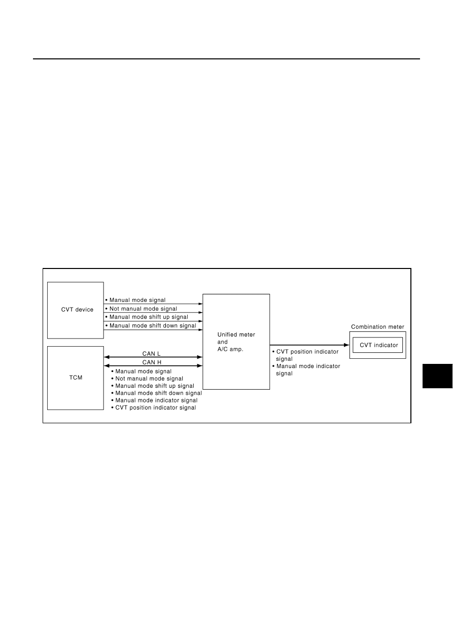
CVT position is displayed in the segment display in the combination meter.

MANUAL MODE

Unified meter and A/C amp. reads manual mode signal and shift-up/down signal from CVT device, and
transmits the signals to TCM with CAN communication.

TCM processes manual mode signal and shift-up/down signal, and transmits manual mode indicator sig-
nal and CVT position indicator signal to unified meter and A/C amp. with CAN communication.

Unified meter and A/C amp. transmits manual mode indicator signal and CVT position indicator signal to
combination meter with the communication line.

Combination meter indicates CVT gear position and manual mode indicator, when receiving manual mode
indicator signal and CVT position indicator signal.

NOT MANUAL MODE

Unified meter and A/C amp. reads not manual mode signal and second position signal from CVT device,
and transmits the signals to TCM with CAN communication.

TCM transmits CVT position indicator signal to unified meter and A/C amp. with CAN communication.

Unified meter and A/C amp. transmits CVT position indicator signal to combination meter with the commu-
nication line.

Combination meter indicates CVT shift position when receiving CVT position indicator signal.

SKIB7447E

DI-52

CVT INDICATOR

Revision: 2006 August

2006 Murano

Wiring Diagram — CVTIND —

NKS001T4

TKWB2612E

CVT INDICATOR

DI-53

C

D

E

F

G

H

I

J

L

M

A

B

DI

Revision: 2006 August

2006 Murano

TKWB0104E

DI-54

CVT INDICATOR

Revision: 2006 August

2006 Murano

TKWB0123E

CVT INDICATOR

DI-55

C

D

E

F

G

H

I

J

L

M

A

B

DI

Revision: 2006 August

2006 Murano

TKWB0124E

DI-56

CVT INDICATOR

Revision: 2006 August

2006 Murano

CVT Indicator Is Malfunction

NKS001T5

1. 

CHECK SEGMENTS OF CVT INDICATOR

Perform self-diagnosis mode of combination meter. Refer to 

DI-15,

"OPERATION PROCEDURE"

 .

Are all segments displayed?

YES

>> GO TO 2.

NO

>> Replace combination meter.

2. 

CHECK UNIFIED METER AND A/C AMP. (CONSULT-II)

Perform self-diagnosis of unified meter and A/C amp. Refer to 

DI-30, "CONSULT-II Function (METER A/C

AMP)"

 .

Self-diagnosis results

No malfunction detected >> GO TO 3.
Malfunction detected >> Check applicable parts, and repair or replace corresponding parts.

3. 

CHECK UNIFIED METER AND A/C AMP. INPUT SIGNAL

1.

Select “DATA MONITOR” of “METER A/C AMP” on CONSULT-II.

2.

Confirm each indication on the monitor when operating the
selector lever.

NOTE:
*: Without manual mode

OK or NG

OK

>> Replace combination meter.

NG

>> GO TO 4.

SKIA4427E

CONSULT-II display

Switch operation

Operation 

status

AT-M IND

Manual mode range

ON

Except for manual mode range

OFF

AT-M GEAR

Manual mode range (shift-up or down)

5-1

Except for manual mode range

1

P RANGE IND

P range position

ON

Except for P range position

OFF

R RANGE IND

R range position

ON

Except for R range position

OFF

N RANGE IND

N range position

ON

Except for N range position

OFF

D RANGE IND

D range position

ON

Except for D range position

OFF

L RANGE IND*

L range position

ON

Except for L range position

OFF

S RANGE IND*

S range position

ON

Except for S range position

OFF

SKIA6259E

CVT INDICATOR

DI-57

C

D

E

F

G

H

I

J

L

M

A

B

DI

Revision: 2006 August

2006 Murano

4. 

CHECK TCM (CONSULT-II)

Perform self-diagnosis of TCM. Refer to 

CVT-60, "CONSULT-II Function (TRANSMISSION)"

 .

Self-diagnosis results

No malfunction detected >> Check TCM input/output signal. Refer to 

CVT-57, "TCM Input/Output Signal Ref-

erence Values"

 .

Malfunction detected >> Check applicable parts, and repair or replace corresponding parts.

DI-58

WARNING CHIME

Revision: 2006 August

2006 Murano

WARNING CHIME

PFP:24814

System Description

NKS001T6

Buzzer for warning chime system is installed in the combination meter.

The buzzer sounds when the combination meter receives buzzer output signal from each unit through uni-
fied meter and A/C amp.

POWER SUPPLY AND GROUND CIRCUIT

Power is supplied at all times

through 50A fusible link (letter F , located in the fuse and fusible link block)

to BCM terminal 55,

through 10A fuse [No. 18, located in the fuse block (J/B)]

to BCM terminal 42,

through 10A fuse [No. 21, located in the fuse block (J/B)] 

to key switch terminal 3 (without Intelligent Key), and

to combination meter terminal 21,

through 10A fuse [No. 22, located in the fuse block (J/B)] 

to key switch and ignition knob switch terminals 1 and 3 (with Intelligent Key),

through 10A fuse [No. 19, located in the fuse block (J/B)] 

to unified meter and A/C amp. terminal 21.

With ignition switch ON or START position, power is supplied

through 10A fuse [No. 1, located in the fuse block (J/B)]

to BCM terminal 38,

through 10A fuse [No. 12, located in the fuse block (J/B)]

to unified meter and A/C amp. terminal 22,

through 10A fuse [No. 14, located in the fuse block (J/B)]

to combination meter terminal 20.

Ground is supplied

to BCM terminal 52

through grounds M14 and M78,

to unified meter and A/C amp. terminals 29 and 30

through grounds M14 and M78,

to combination meter terminals 22, 23 and 24

through grounds M14 and M78.

WARNING CHIME

DI-59

C

D

E

F

G

H

I

J

L

M

A

B

DI

Revision: 2006 August

2006 Murano

IGNITION KEY WARNING CHIME (WITHOUT INTELLIGENT KEY)

With the key inserted into the key switch, and the ignition switch in OFF or ACC position, when driver's door is
opened, the ignition key warning chime will sound.

BCM detects key inserted into the key switch, ignition switch in OFF or ACC position, and front door
switch (driver side) ON. And then transmits buzzer output signal (ignition key warning chime) to unified
meter and A/C amp. with CAN communication.

Unified meter and A/C amp. transmits buzzer output signal (ignition key warning chime) to combination
meter with communication line.

When combination meter receives buzzer output signal (ignition key warning chime), it sounds the buzzer.

IGNITION KEY WARNING CHIME (WITH INTELLIGENT KEY)
When Mechanical Key Is Used

With the key inserted into the ignition switch, and the ignition switch LOCK or ACC position, when driver's door
is opened, the warning chime will sound.

BCM detects key inserted into the key switch, ignition switch in LOCK or ACC position, and front door
switch (driver side) ON. And then transmits buzzer output signal (ignition key warning chime) to unified
meter and A/C amp. with CAN communication.

Unified meter and A/C amp. transmits buzzer output signal (ignition key warning chime) to combination
meter with communication line.

When combination meter receives buzzer output signal (ignition key warning chime), it sounds the buzzer.

When Intelligent Key Is Carried With The Driver

Refer to 

BL-101, "WARNING CHIME FUNCTION"

 .

SKIB6481E

SKIB7258E

DI-60

WARNING CHIME

Revision: 2006 August

2006 Murano

LIGHT WARNING CHIME

With ignition switch in OFF or ACC position, driver's door is opened, and lighting switch in 1ST or 2ND posi-
tion, the light warning chime will sound. 

BCM detects ignition switch in OFF or ACC position, front door switch (driver side) ON, and lighting switch
in 1ST or 2ND position. And then transmits buzzer output signal (light warning chime) to unified meter and
A/C amp. with CAN communication.

Unified meter and A/C amp. transmits buzzer output signal (light warning chime) to combination meter
with communication line.

When combination meter receives buzzer output signal (light warning chime), it sounds the buzzer.

NOTE:
For further details of combination switch, refer to 

LT-144, "Combination Switch Reading Function"

 .

SEAT BELT WARNING CHIME

With ignition switch turned ON and driver's seat belt unfastened, seat belt warning chime will sound for
approximately 6 seconds.

Combination meter reads a ON/OFF signal from seat belt buckle switch (driver side), and transmits seat
belt buckle switch signal to unified meter and A/C amp. with communication line.

BCM receives seat belt buckle switch signal from unified meter and A/C amp. with CAN communication.

BCM detects ignition switch turned ON and seat belt buckle switch (driver side) ON. And then transmits
buzzer output signal (seat belt warning chime) to unified meter and A/C amp. with CAN communication.

Unified meter and A/C amp. transmits buzzer output signal (seat belt warning chime) to combination
meter with communication line.

When combination meter receives buzzer output signal (seat belt warning chime), it sounds the buzzer.

NOTE:
When ignition key warning chime, light warning chime, and seat belt warning chime should be conducted at
the same time, the priorities for each chime are the following.

1.

Light warning chime

2.

Ignition key warning chime

3.

Seat belt warning chime

SKIB3858E

SKIB6482E

WARNING CHIME

DI-61

C

D

E

F

G

H

I

J

L

M

A

B

DI

Revision: 2006 August

2006 Murano

Component Parts and Harness Connector Location

NKS001T9

SKIB7449E

DI-62

WARNING CHIME

Revision: 2006 August

2006 Murano

Schematic

NKS001TA

TKWB0491E

WARNING CHIME

DI-63

C

D

E

F

G

H

I

J

L

M

A

B

DI

Revision: 2006 August

2006 Murano

Wiring Diagram — CHIME —

NKS001TB

TKWB0492E

DI-64

WARNING CHIME

Revision: 2006 August

2006 Murano

TKWB2613E

WARNING CHIME

DI-65

C

D

E

F

G

H

I

J

L

M

A

B

DI

Revision: 2006 August

2006 Murano

TKWB0494E

DI-66

WARNING CHIME

Revision: 2006 August

2006 Murano

Terminals and Reference Value for BCM

NKS001TC

CAUTION:

Check combination switch system terminal waveform under the loaded condition with lighting
switch, turn signal and wiper switch OFF not to be fluctuated by overloaded.

Turn wiper dial position to 4 except when checking waveform or voltage of wiper dial position.
Wiper dial position can be confirmed on CONSULT-II. Refer to 

LT-149, "DATA MONITOR"

 .

Ter-

mina

l No.

Wire 

color

Signal name

Measuring condition

Reference value (V)

Ignition 

switch

Operation or condition

2

R

Combination 
switch input 5

ON

Lighting, 
turn, wiper 
switch
(Wiper 
intermit-
tent dial 
position 4)

OFF

Approx. 0

Any of the conditions below

Lighting switch 1ST

Lighting switch HIGH beam
(Operates only HIGH beam switch)

Turn signal switch to right

Approx. 1.0

Lighting switch 2ND

Approx. 2.0

3

P/L

Combination 
switch input 4

ON

Lighting, 
turn, wiper 
switch
(Wiper 
intermit-
tent dial 
position 4)

OFF

Approx. 0

Front fog lamp switch (Operates only 
front fog lamp switch)

Approx. 0.8

Any of the conditions below

Lighting switch 2ND

Lighting switch PASSING
(Operates only PASSING switch)

Turn signal switch to left

Approx. 1.0

4

R/G

Combination 
switch input 3

ON

Lighting, 
turn, wiper 
switch
(Wiper 
intermit-
tent dial 
position 4)

OFF

Approx. 0

Any of the conditions below

Lighting switch AUTO

Front wiper switch MIST

Front wiper switch INT

Front wiper switch LO

Approx. 1.0

PKIB4959J

PKIB4953J

PKIB4955J

PKIB4959J

PKIB4959J


Content      ..     72      73      74      75     ..