Nissan Murano Z50 (2006 year). Manual - part 75
WARNING CHIME
DI-67
C
D
E
F
G
H
I
J
L
M
A
B
DI
Revision: 2006 August
2006 Murano
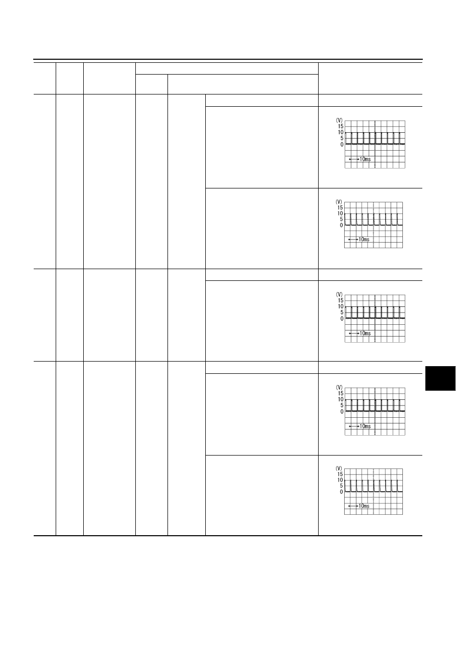
5
R/B
Combination
switch input 2
ON
Lighting,
turn, wiper
switch
OFF
Approx. 0
Any of the conditions below
●
Front washer switch
(Wiper intermittent dial position 4)
●
Rear washer switch
(Wiper intermittent dial position 4)
●
Wiper intermittent dial position 1
●
Wiper intermittent dial position 5
●
Wiper intermittent dial position 6
Approx. 1.0
Rear wiper switch ON
(Wiper intermittent dial position 4)
Approx. 0.8
4
R/G
Combination
switch input 3
ON
Lighting,
turn, wiper
switch
(Wiper
intermit-
tent dial
position 4)
OFF
Approx. 0
Any of the conditions below
●
Lighting switch AUTO
●
Front wiper switch MIST
●
Front wiper switch INT
●
Front wiper switch LO
Approx. 1.0
5
R/B
Combination
switch input 2
ON
Lighting,
turn, wiper
switch
OFF
Approx. 0
Any of the conditions below
●
Front washer switch
(Wiper intermittent dial position 4)
●
Rear washer switch
(Wiper intermittent dial position 4)
●
Wiper intermittent dial position 1
●
Wiper intermittent dial position 5
●
Wiper intermittent dial position 6
Approx. 1.0
Rear wiper switch ON
(Wiper intermittent dial position 4)
Approx. 0.8
Ter-
mina
l No.
Wire
color
Signal name
Measuring condition
Reference value (V)
Ignition
switch
Operation or condition
PKIB4959J
PKIB4955J
PKIB4959J
PKIB4959J
PKIB4955J