Nissan Murano Z50 (2006 year). Manual - part 72


  Index      Manuals     Nissan Murano Z50 (2006 year) - Service and Repair Manual


Search            copyright infringement  


Content      ..     70      71      72      73     ..


Nissan Murano Z50 (2006 year). Manual - part 72


COMBINATION METERS

DI-19

C

D

E

F

G

H

I

J

L

M

A

B

DI

Revision: 2006 August

2006 Murano

3. 

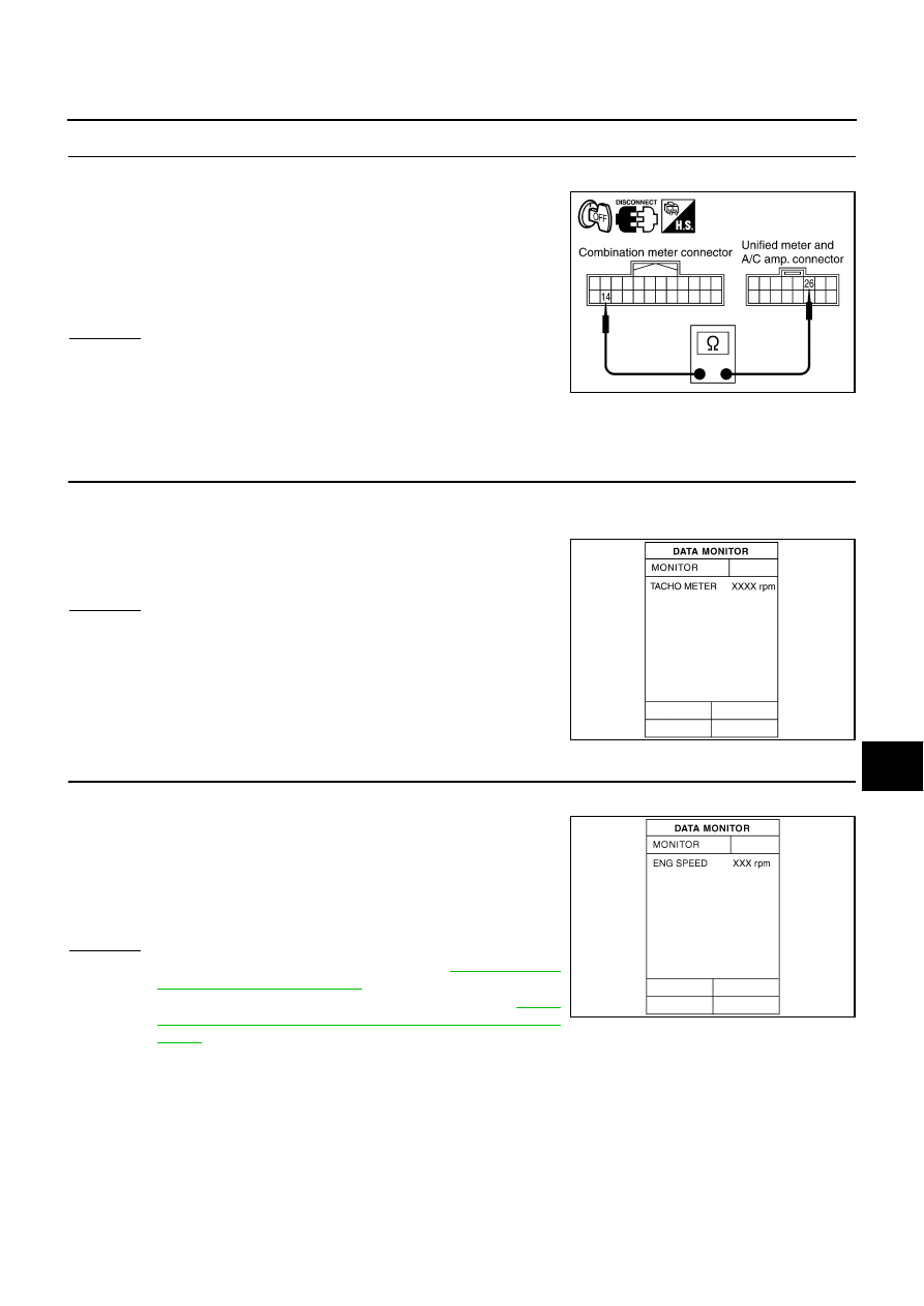
CHECK CONTINUITY BETWEEN COMBINATION METER AND UNIFIED METER AND A/C AMP. 

1.

Turn ignition switch OFF.

2.

Disconnect combination meter connector and unified meter and
A/C amp. connector.

3.

Check continuity between combination meter harness connector
M25 terminal 14 and unified meter and A/C amp. harness con-
nector M50 terminal 26. 

OK or NG

OK

>> Replace combination meter.

NG

>> Repair harness or connector.

Engine Speed Signal Inspection 

NKS002CJ

Symptom: Tachometer indication is malfunction.

1. 

CHECK COMBINATION METER INPUT SIGNAL

1.

Connect CONSULT-II, and start engine.

2.

Select “METER A/C AMP” on CONSULT-II.

3.

Using “TACHO METER” on “DATA MONITOR”, compare the
value of “DATA MONITOR” with tachometer pointer of combina-
tion meter. 

OK or NG

OK

>> GO TO 2.

NG

>> Replace combination meter.

2. 

CHECK UNIFIED METER AND A/C AMP. INPUT SIGNAL

1.

Select “ENGINE” on CONSULT-II.

2.

Using “ENG SPEED” on “DATA MONITOR”, print out the CON-
SULT-II screen when the engine is idling.

3.

Select “METER A/C AMP” on CONSULT-II.

4.

Using “TACHO METER” on “DATA MONITOR”, compare the
value of “DATA MONITOR” of the idling speed with that of the
“ENG SPEED”.

OK or NG

OK

>> Perform self-diagnosis of ECM. Refer to 

EC-112, "CON-

SULT-II Function (ENGINE)"

 .

NG

>> Replace unified meter and A/C amp. Refer to 

DI-37,

"Removal and Installation of Unified Meter and A/C
Amp."

 .

14 – 26

: Continuity should exist.

PKIB3976E

PKIA2090E

SKIA4367E

DI-20

COMBINATION METERS

Revision: 2006 August

2006 Murano

Engine Coolant Temperature Signal Inspection

NKS002CK

Symptom: Water temperature gauge indication is malfunction.

1. 

CHECK COMBINATION METER INPUT SIGNAL

1.

Connect CONSULT-II, and start engine.

2.

Select “METER A/C AMP” on CONSULT-II.

3.

Using “W TEMP METER” on “DATA MONITOR”, compare the
value of “DATA MONITOR” with water temperature gauge
pointer of combination meter. 

OK or NG

OK

>> GO TO 2.

NG

>> Replace combination meter.

2. 

CHECK UNIFIED METER AND A/C AMP. INPUT SIGNAL

1.

Select “ENGINE” on CONSULT-II.

2.

Using “COOLAN TEMP/S” on “DATA MONITOR”, print out the
CONSULT-II screen.

3.

Select “METER A/C AMP” on CONSULT-II.

4.

Using “W TEMP METER” on “DATA MONITOR”, compare the
value of data monitor with that of the “COOLAN TEMP/S”.

OK or NG

OK

>> Perform self-diagnosis of ECM. Refer to 

EC-112, "CON-

SULT-II Function (ENGINE)"

 .

NG

>> Replace unified meter and A/C amp. Refer to 

DI-37,

"Removal and Installation of Unified Meter and A/C
Amp."

 .

Fuel Level Sensor Signal Inspection

NKS002CL

Symptom:

Fuel gauge indication is malfunction.

Low-fuel warning lamp indication is irregular.

NOTE:
The following symptoms are not malfunction.

Fuel gauge

Depending on vehicle position or driving circumstance, the fuel level in the tank various, and the pointer
may fluctuate.

If the vehicle is fueled with the ignition switch ON, the pointer will move slowly.

Low-fuel warning lamp

Depending on vehicle position or driving circumstance, the fuel in the tank flows and the warning lamp ON
timing may change.

Water temperature gauge pointer

Reference value of data monitor [

°

C (

°

F)]

Hot

Approx. 130 (266)

Middle

Approx. 70 - 105 (158 - 221)

Cold

Approx. 50 (122)

PKIA2091E

SKIA4368E

COMBINATION METERS

DI-21

C

D

E

F

G

H

I

J

L

M

A

B

DI

Revision: 2006 August

2006 Murano

1. 

CHECK COMBINATION METER INPUT SIGNAL

1.

Select “METER A/C AMP” on CONSULT-II.

2.

Using “FUEL METER” on “DATA MONITOR”, compare the value
of “DATA MONITOR” with fuel gauge pointer of combination
meter. 

OK or NG

OK

>> GO TO 2.

NG

>> Replace combination meter.

2. 

CHECK FUEL LEVEL SENSOR (MAIN) CIRCUIT 1

1.

Turn ignition switch OFF.

2.

Disconnect fuel level sensor unit and fuel pump (main) connec-
tor and unified meter and A/C amp. connector.

3.

Check continuity between fuel level sensor unit and fuel pump
(main) harness connector B17 terminal 2 and unified meter and
A/C amp. harness connector M50 terminal 28. 

4.

Check continuity between fuel level sensor unit and fuel pump
(main) harness connector B17 terminal 2 and ground.

OK or NG

OK

>> GO TO 3.

NG

>> Repair harness or connector.

3. 

CHECK FUEL LEVEL SENSOR (MAIN) CIRCUIT 2

1.

Check continuity between fuel level sensor unit and fuel pump
(main) harness connector B17 terminal 5 and unified meter and
A/C amp. harness connector M50 terminal 36.

2.

Check continuity between fuel level sensor unit and fuel pump
(main) harness connector B17 terminal 5 and ground.

OK or NG

OK

>> GO TO 4.

NG

>> Repair harness or connector.

Fuel gauge pointer

Reference value of data monitor [lit.]

Full

Approx. 78

Three quarters

Approx. 63

Half

Approx. 43

A quarter

Approx. 22

Empty

Approx. 7

PKIA2088E

2 – 28

: Continuity should exist.

2 – Ground

: Continuity should not exist.

PKIB3977E

5 – 36

: Continuity should exist.

5 – Ground

: Continuity should not exist.

PKIB3978E

DI-22

COMBINATION METERS

Revision: 2006 August

2006 Murano

4. 

CHECK FUEL LEVEL SENSOR

Check components. Refer to 

DI-23, "FUEL LEVEL SENSOR UNIT"

 .

OK or NG

OK

>> Check fuel level sensor unit installation, and check whether the float arm interferes or binds with

any of the internal components in the fuel tank. Repair or replace malfunctioning part, if neces-
sary.

NG

>> Replace fuel level sensor unit.

Fuel Gauge Pointer Fluctuates, Indicator Wrong Value or Varies

NKS002CN

1. 

CHECK FUEL GAUGE FLUCTUATION

Test drive vehicle to see if gauge fluctuates only during driving or at the instant of stopping.

Does the indication value vary only during driving or at the instant of stopping?

YES

>> The pointer fluctuation may be caused by fuel level change in the fuel tank. Condition is normal.

NO

>> Ask the customer about the situation when the symptom occurs in detail, and perform the trouble

diagnosis.

Fuel Gauge Does Not Move to FULL Position

NKS002CO

1. 

QUESTION 1

Does it take a long time for the pointer to move to FULL position?

YES

>> GO TO 2.

NO

>> GO TO 3.

2. 

QUESTION 2

Was the vehicle fueled with the ignition switch ON?

YES

>> Be sure to fuel the vehicle with the ignition switch OFF. Otherwise, it will take a long time to move

to FULL position because of the characteristic of the fuel gauge.

NO

>> GO TO 3.

3. 

QUESTION 3

Is the vehicle parked on an incline?

YES

>> Check the fuel level indication with vehicle on a level surface.

NO

>> GO TO 4.

4. 

QUESTION 4

During driving, does the fuel gauge pointer move gradually toward EMPTY position?

YES

>> Check the fuel level sensor unit. Refer to 

DI-23, "FUEL LEVEL SENSOR UNIT"

 .

NO

>> The float arm may interfere or bind with any of the components in the fuel tank.

COMBINATION METERS

DI-23

C

D

E

F

G

H

I

J

L

M

A

B

DI

Revision: 2006 August

2006 Murano

Odo/Trip Meter and Illumination Control Switch Inspection

NKS002CM

Symptom: Illumination control does not operate.

1. 

CHECK ODO/TRIP METER AND ILLUMINATION CONTROL SWITCH

1.

Remove combination meter. Refer to 

DI-24, "Removal and Installation of Combination Meter"

 .

2.

Remove meter lid. Refer to 

DI-24, "Disassembly and Assembly of Combination Meter"

 .

3.

Check odo/trip meter and illumination control switch. Refer to 

DI-23, "ODO/TRIP METER AND ILLUMI-

NAION CONTROL SWITCH"

 .

OK or NG

OK

>> Check harness between combination meter and odo/trip meter and illumination control switch.

Replace combination meter if the results of the check are normal.

NG

>> Replace odo/trip meter and illumination control switch.

Electrical Components Inspection

NKS002CP

ODO/TRIP METER AND ILLUMINAION CONTROL SWITCH

Check continuity between terminals 3, 4 or 5 and 6.

FUEL LEVEL SENSOR UNIT

For removal, refer to 

FL-4, "FUEL LEVEL SENSOR UNIT, FUEL FILTER AND FUEL PUMP ASSEMBLY"

 .

Fuel Level Sensor Unit and Fuel Pump (Main) 

Check resistance between fuel level sensor unit and fuel pump
(main) connector terminals 2 and 6.

*1 and *2: When float rod is in contact with stopper.

Fuel Level Sensor Unit and Pump (Main) Harness

Check continuity between fuel level sensor unit and fuel pump
(main) connector terminals 5 and 7.

Terminal

Condition

Continuity

3

6

Illumination control switch (+) is pressed.

Yes

Illumination control switch (+) is released.

No

4

Illumination control switch (–) is pressed.

Yes

Illumination control switch (–) is released.

No

5

Odo/trip meter switch is pressed.

Yes

Odo/trip meter switch is released.

No

PKIB3985E

Terminal

Float position

[mm (in)]

Resistance value [

]

2

6

*1

Empty

15 (0.59)

Approx. 81.5

*2

Full

193 (7.6)

Approx. 2.5

PKIB6087E

5 – 7

: Continuity should exist.

PKIA2596E

DI-24

COMBINATION METERS

Revision: 2006 August

2006 Murano

Fuel Level Sensor Unit (Sub)

Check resistance between fuel level sensor unit and fuel pump
(main) connector terminals 6 and 7.

*1 and *2: When float rod is in contact with stopper.

Removal and Installation of Combination Meter

NKS002CQ

REMOVAL

1.

Remove instrument driver lower panel. Refer to 

IP-10, "INSTRUMENT PANEL ASSEMBLY"

 .

2.

Remove steering column cover. Refer to 

IP-10, "INSTRUMENT PANEL ASSEMBLY"

 .

3.

Remove bolts (2) and remove combination meter.

INSTALLATION

Installation is the reverse order of removal.

Disassembly and Assembly of Combination Meter

NKS002CR

Terminal

Float position

[mm (in)]

Resistance value [

]

6

7

*1

Empty

10 (0.39)

Approx. 45.2

*2

Full

198 (7.8)

Approx. 2.5

PKIB6088E

PKIB7435E

1.

Switch cover (Left side)

2.

Screws

3.

Unified meter control unit assembly

4.

Screws

5.

Odo/trip meter and illumination con-
trol switch

6.

Meter lid

7.

Hazard switch

8.

Screws

9.

Bracket

10. Switch cover (Right side)

11. Screws

12. Rear cover

SKIB7557E

COMBINATION METERS

DI-25

C

D

E

F

G

H

I

J

L

M

A

B

DI

Revision: 2006 August

2006 Murano

DISASSEMBLY

1.

Remove screws (A). 

2.

Disengaged the tabs (A) and remove meter lid.

3.

Disconnect odo/trip meter and illumination control switch and
hazard switch connectors.

4.

Remove screws (A) and remove odo/trip meter and illumination
control switch.

5.

Disengaged the tabs (A) and remove hazard switch (1).

SKIB7558E

SKIB7559E

SKIB7560E

SKIB7561E

DI-26

COMBINATION METERS

Revision: 2006 August

2006 Murano

6.

Remove screws (A) and remove switch cover.

7.

Remove screws (A) and remove rear cover.

8.

Disengaged the tabs (A) to separate bracket.

ASSEMBLY

Assembly is the reverse order of disassembly.

SKIB7562E

SKIB7563E

SKIB7564E

UNIFIED METER AND A/C AMP

DI-27

C

D

E

F

G

H

I

J

L

M

A

B

DI

Revision: 2006 August

2006 Murano

UNIFIED METER AND A/C AMP

PFP:27760

System Description

NKS001SN

For the unified meter and A/C amp., the signal required for controlling the combination meter are inte-
grated in the A/C auto amp.

The unified meter and A/C amp. corresponds to a CONSULT-II function (self-diagnosis results, CAN diag-
nosis support monitor, data monitor).

COMBINATION METER CONTROL FUNCTION

Unified meter and A/C amp. receives necessary information for combination meter from each unit by CAN
communication.

Unified meter and A/C amp. transmits a signals with communication line (TX, RX) between unified meter
and A/C amp. and combination meter.

Input/output signals between unified meter and A/C amp. and combination meter.

NOTE:
Combination meter performs fail-safe operation when unified meter and A/C amp. communication is malfunction. Refer to 

DI-7, "FAIL-

SAFE"

 .

Unit

Input

Output

Unified meter and A/C amp.

Seat belt buckle switch signal (Driver's side)

Parking brake signal

Illumination control nighttime required signal

Refuel status signal

Low-fuel warning lamp condition signal

Combination meter receive error signal

Delivery destination data signal

Combination meter specifications signal

Vehicle speed signal (8-pulse)

Engine speed signal

Engine coolant temperature signal

Fuel level sensor signal (resistance value)

Malfunction indicator signal

ABS warning lamp signal

Low tire pressure warning signal

Brake warning lamp signal

AWD warning lamp signal

Turn indicator signal

High beam request signal

VDC OFF indicator lamp signal

SLIP indicator lamp signal

CRUISE indicator lamp signal

SET indicator lamp signal

AWD lock indicator lamp signal

CVT indicator lamp signal

CVT position indicator signal

Manual mode indicator signal

Manual mode gear position signal

Second position indicator signal

CAN communication condition signal of CVT

Door switch signal

Oil pressure switch signal

Position lights request signal

Buzzer output signal

DI-28

UNIFIED METER AND A/C AMP

Revision: 2006 August

2006 Murano

A/C AUTO AMP. FUNCTION

Unified meter and A/C amp. controls each operation for A/C auto amp. Regarding A/C control, refer to 

ATC-

25, "AIR CONDITIONER CONTROL"

   in ATC section.

OTHER FUNCTIONS
Drive Computer Function

The signals required for the distance to empty (DTE) display are centralized in the unified meter and A/C
amp., converted into data, and sent to the display unit (without NAVI) or display control unit (with NAVI) using
CAN communication.

Signal Buffer Function

Unified meter and A/C amp. transmits each signal to other units with CAN communication.

UNIFIED METER AND A/C AMP

DI-29

C

D

E

F

G

H

I

J

L

M

A

B

DI

Revision: 2006 August

2006 Murano

Schematic

NKS001SQ

TKWB2601E

DI-30

UNIFIED METER AND A/C AMP

Revision: 2006 August

2006 Murano

CONSULT-II Function (METER A/C AMP)

NKS001SR

CONSULT-II can display each diagnostic item using the diagnostic test modes shown following.

CONSULT-II BASIC OPERATION

CAUTION:

If CONSULT-II is used with no connection of CONSULT-II CONVERTER, malfunctions might be
detected in self-diagnosis depending on control unit which carry out CAN communication.

1.

With the ignition switch OFF, connect “CONSULT-II” and “CON-
SULT-II CONVERTER” to the data link connector, and then turn
ignition switch ON.

2.

Touch “START (NISSAN BASED VHCL)”.

3.

Touch “METER A/C AMP” on “SELECT SYSTEM” screen. If
“METER A/C AMP” is not indicated, go to 

GI-39, "CONSULT-II

Data Link Connector (DLC) Circuit"

 .

System

Diagnosis mode

Description

Reference 

page

METER A/C AMP

SELF-DIAG RESULTS

Unified meter and A/C amp. checks the conditions and dis-
plays memorized error.

DI-31

CAN DIAG SUPPORT MNTR

The results of transmit/receive diagnosis of CAN communica-
tion can be read.

LAN-17

DATA MONITOR

Displays unified meter and A/C amp. input data in real time.

DI-32

PBIB1300E

BCIA0029E

BCIA0030E

UNIFIED METER AND A/C AMP

DI-31

C

D

E

F

G

H

I

J

L

M

A

B

DI

Revision: 2006 August

2006 Murano

4.

Select “SELF-DIAG RESULTS”, “CAN DIAG SUPPORT MNTR”
or “DATA MONITOR” on “SELECT DIAG MODE” screen. 

SELF-DIAG RESULTS
Operation Procedure

1.

Touch “SELF-DIAG RESULTS” on “SELECT DIAG MODE” screen.

2.

Self-diagnosis results are displayed.

Display Item List

NOTE:
“TIME” means the following.

0: Means detected malfunction at present. (From malfunction detection to turning ignition switch OFF)

1 - 63: Means detected malfunction in past. (Displays number of ignition switch OFF 

 ON after detecting

malfunction. “SELF-DIAG RESULTS” is erased when exceeding “63”.)

CAUTION:

“TIME” keeps showing “0” after returning to normal condition only in the case that malfunction his-
tory of “CAN COMM CIRC [U1000]” remains because of display control unit (with NAVI) or display unit
(without NAVI) malfunction.

BCIA0031E

SKIA4956E

CONSULT-ll display

Malfunction is detected when...

Reference 

page

CAN COMM CIRC 
[U1000]

Malfunction is detected in CAN communication.

CAUTION:

Even when there is no malfunction on CAN communication system, malfunction may 
be misinterpreted when battery has low voltage (when maintaining 7 - 8 V for about 2 
seconds) or 10A fuse [No. 19, located in the fuse block (J/B)] is disconnected.

DI-34

METER COMM CIRC
[B2202]

Malfunction is detected in communication of between combination meter and unified meter 
and A/C amp.

DI-34

VEHICLE SPEED 
CIRC
[B2205]

When an erroneous speed signal is input for 1 second.

CAUTION:

Even when there is no malfunction on speed signal system, malfunction may be misin-
terpreted when battery has low voltage (when maintaining 7 - 8 V for about 2 seconds). 

DI-37

DI-32

UNIFIED METER AND A/C AMP

Revision: 2006 August

2006 Murano

DATA MONITOR
Operation Procedure

1.

Touch “DATA MONITOR” on “SELECT DIAG MODE” screen.

2.

Touch “MAIN SIGNALS” or “SELECTION FROM MENU” on the “DATA MONITOR” screen.

3.

When “SELECTION FROM MENU” is selected, touch individual items to be monitored. When “MAIN SIG-
NALS” is selected, main items will be monitored.

4.

Touch “START”.

5.

Touch “RECORD” while monitoring, then the status of the moni-
tored item can be recorded. To stop recording, touch “STOP”.

Display Item List

MAIN SIGNALS

Monitors main signals.

SELECTION FROM MENU

Selects and monitors individual signal.

SKIA4957E

Display item [Unit]

MAIN

SIGNALS

SELECTION 

FROM MENU

Contents

SPEED METER [km/h] or [mph]

X

X

Displays the value of vehicle speed signal, which is input from ABS 
actuator and electric unit (control unit).

SPEED OUTPUT [km/h] or [mph]

X

X

Displays the value of vehicle speed signal, which is transmitted to 
each unit with CAN communication.

TACHO METER [rpm]

X

X

Displays the value of engine speed signal, which is input from ECM.

W TEMP METER [

°

C] or [

°

F]

X

X

Displays the value of engine coolant temperature signal, which is 
input from ECM. 

FUEL METER [lit.]

X

X

Displays the value, which processes a resistance signal from fuel 
gauge.

DISTANCE [km] or [mile]

X

X

Displays the value, which is calculated by vehicle speed signal from 
ABS actuator and electric unit (control unit), fuel gauge and fuel 
consumption from ECM.

FUEL W/L [ON/OFF]

X

X

Indicates [ON/OFF] condition of low-fuel warning lamp.

MIL [ON/OFF] 

X

Indicates [ON/OFF] condition of malfunction indicator lamp.

AIR PRES W/L [ON/OFF]

X

Indicates [ON/OFF] condition of low tire pressure warning lamp.

SEAT BELT W/L [ON/OFF]

X

Indicates [ON/OFF] condition of seat belt warning lamp.

BUZZER [ON/OFF]

X

X

Indicates [ON/OFF] condition of buzzer.

DOOR W/L [ON/OFF]

X

Indicates [ON/OFF] condition of door warning lamp.

HI-BEAM IND [ON/OFF]

X

Indicates [ON/OFF] condition of high beam indicator.

TURN IND [ON/OFF]

X

Indicates [ON/OFF] condition of turn indicator.

OIL W/L [ON/OFF]

X

Indicates [ON/OFF] condition of oil pressure warning lamp.

VDC/TCS IND [ON/OFF]

X

Indicates [ON/OFF] condition of VDC/TCS OFF indicator lamp.

ABS W/L [ON/OFF]

X

Indicates [ON/OFF] condition of ABS warning lamp.

SLIP IND [ON/OFF]

X

Indicates [ON/OFF] condition of SLIP indicator lamp.

BRAKE W/L [ON/OFF]*

1

X

Indicates [ON/OFF] condition of brake warning lamp.

M RANGE SW [ON/OFF] 

X

X

Indicates [ON/OFF] condition of manual mode range switch.

NM RANGE SW [ON/OFF]

X

X

Indicates [ON/OFF] condition of except for manual mode range 
switch.

UNIFIED METER AND A/C AMP

DI-33

C

D

E

F

G

H

I

J

L

M

A

B

DI

Revision: 2006 August

2006 Murano

NOTE:
Any monitored item that does not match the vehicle being diagnosed is deleted from the display automatically.
*1: Monitor keeps indicating “OFF” when brake warning lamp is on by the parking brake operation or low brake fluid level. 

Power Supply and Ground Circuit Inspection

NKS002CS

1. 

CHECK FUSE

Check for blown unified meter and A/C amp. fuses.

OK or NG

OK

>> GO TO 2.

NG

>> Be sure to eliminate cause of malfunction before installing new fuse. Refer to 

PG-3, "POWER

SUPPLY ROUTING CIRCUIT"

 .

AT SFT UP SW [ON/OFF]

X

X

Indicates [ON/OFF] condition of CVT shift-up switch.

AT SFT DWN SW [ON/OFF]

X

X

Indicates [ON/OFF] condition of CVT shift-down switch.

O/D OFF SW [ON/OFF]

X

Indicates [ON/OFF] condition of SPORT mode switch (second posi-
tion switch).

BRAKE SW [ON/OFF]

X

Indicates [ON/OFF] condition of brake switch (stop lamp switch).

AT-M IND [ON/OFF]

X

X

Indicates [ON/OFF] condition of CVT manual mode indicator.

AT-M GEAR [5-1]

X

X

Indicates [5-1] condition of CVT manual mode gear position.

P RANGE IND [ON/OFF] 

X

X

Indicates [ON/OFF] condition of CVT shift P range indicator.

R RANGE IND [ON/OFF]

X

X

Indicates [ON/OFF] condition of CVT shift R range indicator.

N RANGE IND [ON/OFF]

X

X

Indicates [ON/OFF] condition of CVT shift N range indicator.

D RANGE IND [ON/OFF]

X

X

Indicates [ON/OFF] condition of CVT shift D range indicator.

L RANGE IND [ON/OFF]

X

X

Indicates [ON/OFF] condition of CVT shift L range indicator.

CVT IND [ON/OFF]

X

Indicates [ON/OFF] condition of CVT indicator.

S RANGE IND [ON/OFF]

X

X

Indicates [ON/OFF] condition of CVT shift S range indicator.

CRUISE IND [ON/OFF]

X

Indicates [ON/OFF] condition of CRUISE indicator.

SET IND [ON/OFF]

X

Indicates [ON/OFF] condition of SET indicator.

4WD LOCK SW [ON/OFF]

X

Indicates [ON/OFF] condition of AWD lock switch.

4WD LOCK IND [ON/OFF]

X

Indicates [ON/OFF] condition of AWD lock indicator lamp.

4WD W/L [ON/OFF]

X

Indicates [ON/OFF] condition of AWD warning lamp.

RR COMB STATE [OK/NG]

X

Indicates [OK/NG] condition of rear combination lamp circuit.

Display item [Unit]

MAIN

SIGNALS

SELECTION 

FROM MENU

Contents

Power source

Fuse No.

Battery power supply

19

Ignition power supply (ON or START)

12

Ignition power supply (ON)

10, 11

DI-34

UNIFIED METER AND A/C AMP

Revision: 2006 August

2006 Murano

2. 

CHECK POWER SUPPLY CIRCUIT

Check voltage between unified meter and A/C amp. harness con-
nector terminals and ground.

OK or NG

OK

>> GO TO 3.

NG

>> Check harness between unified meter and A/C amp. and fuse.

3. 

CHECK GROUND CIRCUIT

1.

Turn ignition switch OFF.

2.

Disconnect unified meter and A/C amp. connector.

3.

Check continuity between unified meter and A/C amp. harness
connector M50 terminals 29, 30 and ground.

OK or NG

OK

>> INSPECTION END

NG

>> Repair harness or connector.

DTC [U1000] CAN Communication Circuit

NKS001SS

Symptom: Display “CAN COMM CIRC [U1000]” at the result of self-diagnosis for unified meter and A/C amp.

1. 

CHECK CAN COMMUNICATION 

1.

Select “SELF-DIAG RESULTS” mode for “METER A/C AMP” with CONSULT-II.

2.

Print out CONSULT-II screen.

>> Go to “LAN system”. Refer to 

LAN-3, "Precautions When Using CONSULT-II"

 .

DTC [B2202] Meter Communication Circuit

NKS001ST

Symptom: Display “METER COMM CIRC [B2202]” at the result of self-diagnosis for unified meter and A/C
amp.

1. 

CHECK CONNECTOR

Check combination meter, unified meter and A/C amp. and terminals (combination meter side, unified meter
and A/C amp. side and harness side) for looseness or bent terminals.

OK or NG

OK

>> GO TO 2.

NG

>> Repair terminal or connector.

Terminals

Ignition switch position

(+)

(–)

OFF

ON

Connector

Terminal

M50

21

Ground

Battery voltage

Battery voltage

22

0 V

Battery voltage

M51

46

0 V

Battery voltage

PKIB3971E

29 – Ground

: Continuity should exist.

30 – Ground

PKIB3973E


Content      ..     70      71      72      73     ..