Nissan Murano Z50 (2006 year). Manual - part 70
CVT FLUID COOLER VALVE
CVT-225
D
E
F
G
H
I
J
K
L
M
A
B
CVT
Revision: 2006 August
2006 Murano
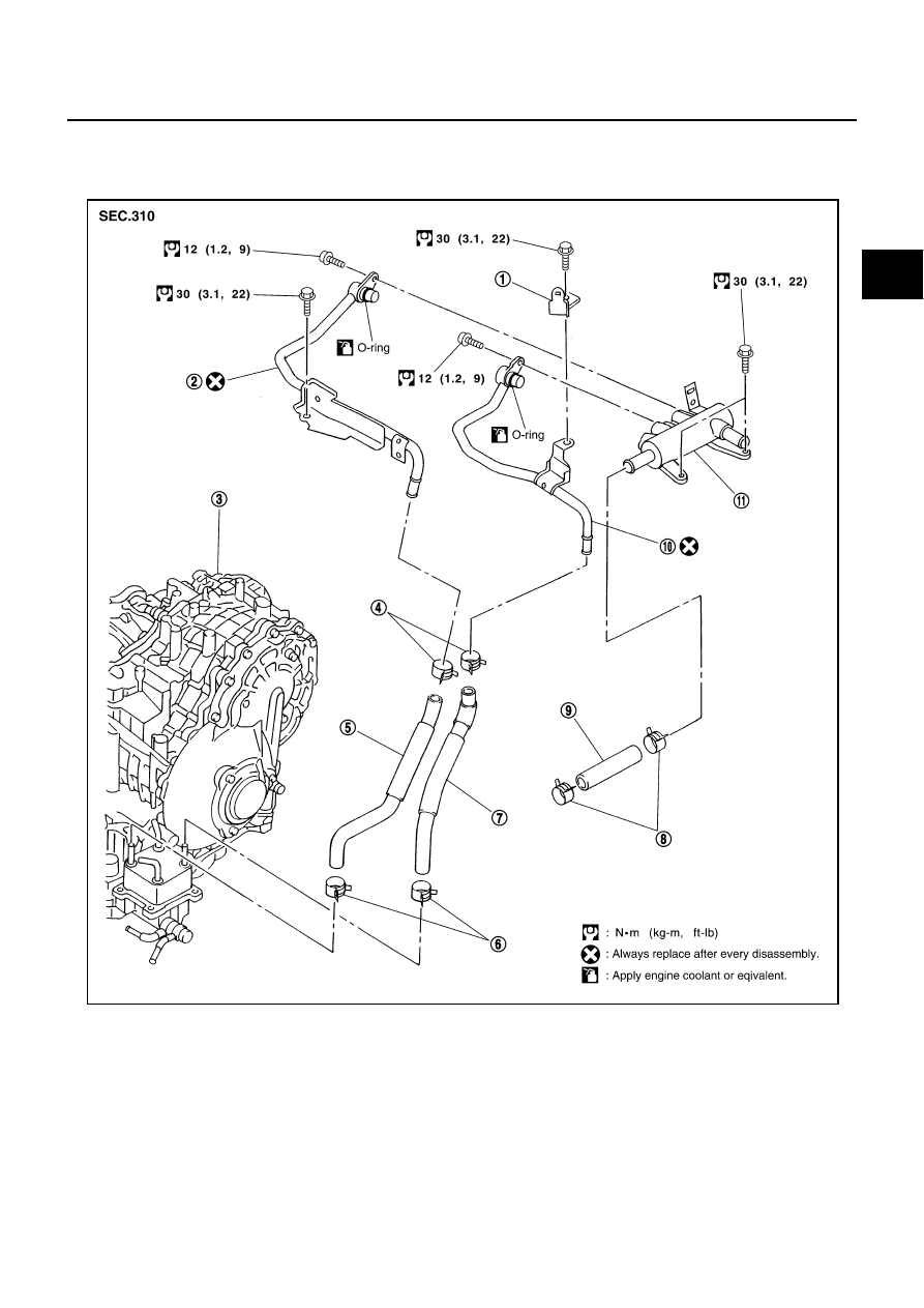
CVT FLUID COOLER VALVE
PFP:21630
Removal and Installation
NCS0019J
COMPONENTS
1.
Harness bracket
2.
CVT fluid cooler inlet tube assembly 3.
Transaxle assembly
4.
Hose clamp
5.
Inlet water hose
6.
Hose clamp
7.
Outlet water hose
8.
Hose clamp
9.
Heater hose
10. CVT fluid cooler outlet tube assem-
bly
11.
CVT fluid cooler valve assembly
SCIA4344E