Nissan Murano Z50 (2005 year). Manual - part 215
AUTOMATIC DRIVE POSITIONER
SE-81
C
D
E
F
G
H
J
K
L
M
A
B
SE
Revision: 2005 August
2005 Murano
2.
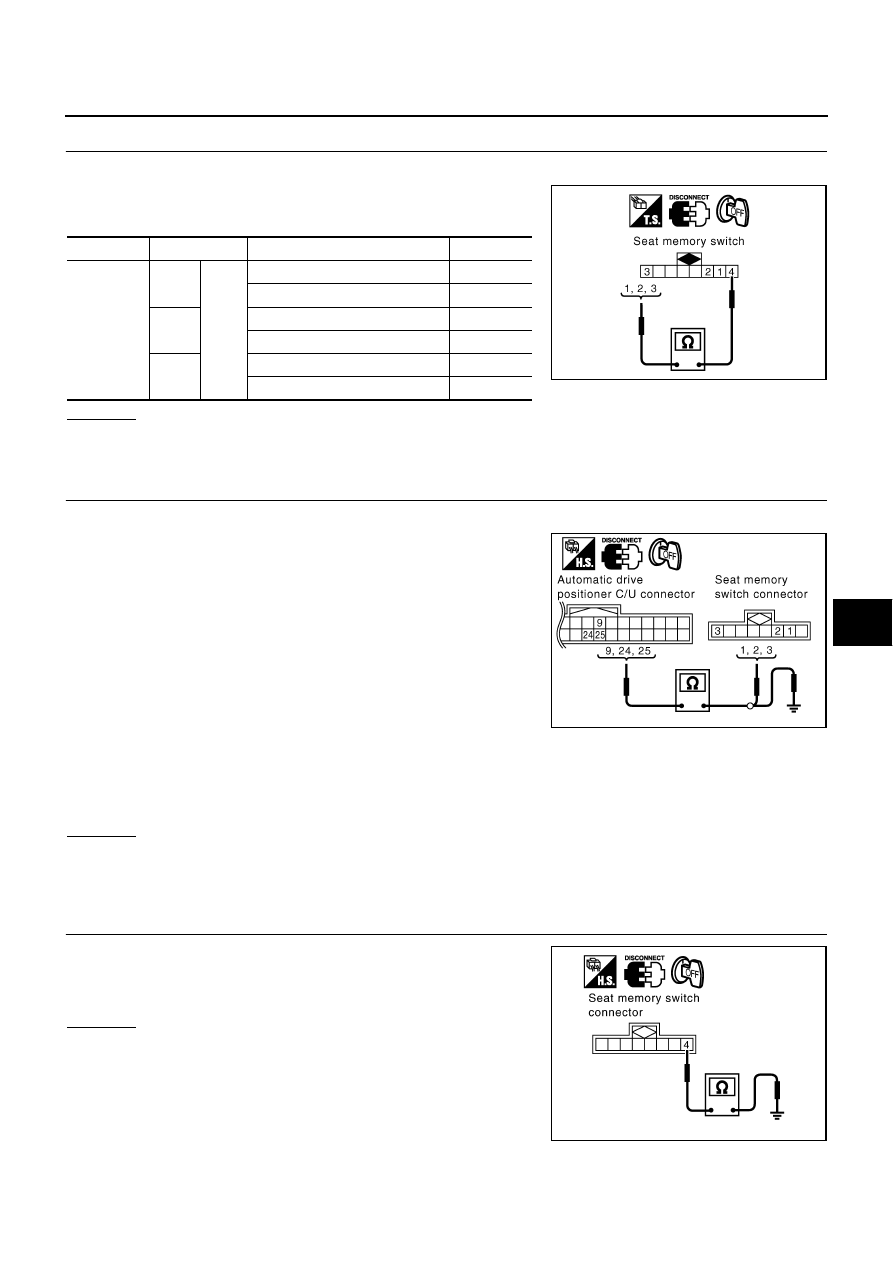
CHECK SEAT MEMORY SWITCH
1.
Turn ignition switch OFF.
2.
Disconnect seat memory switch connector.
3.
Check continuity between seat memory switch as follows.
OK or NG
OK
>> GO TO 3.
NG
>> Replace seat memory switch.
3.
CHECK HARNESS CONTINUITY
1.
Disconnect automatic drive positioner control unit connector.
2.
Check continuity between automatic drive positioner control unit
connector M19 terminals 9 (LG/B), 24 (R/Y), 25 (P/L) and seat
memory switch connector D3 terminals 1 (LG/B), 2 (P/L), 3 (R/
Y).
3.
Check continuity between automatic drive positioner control unit
connector M19 terminals 9 (LG/B), 24 (R/Y), 25 (P/L) and
ground.
OK or NG
OK
>> GO TO 4.
NG
>> Repair or replace harness between automatic drive positioner control unit and seat memory
switch.
4.
CHECK SEAT MEMORY SWITCH GROUND CIRCUIT
Check continuity between seat memory switch D3 terminal 4 (B) and
ground.
OK or NG
OK
>> Replace automatic drive positioner control unit.
NG
>> Repair or replace harness between seat memory switch
and ground.
Connector
Terminal
Condition
Continuity
D3
1
4
Memory switch 1 ON
Yes.
Memory switch 1: OFF
No.
2
Memory switch 2: ON
Yes.
Memory switch 2: OFF
No.
3
Set switch: ON
Yes.
Set switch: OFF
No.
PIIA4575E
9 (LG/B) – 1 (LG/B)
: Continuity should exist.
24 (R/Y) – 3 (R/Y)
: Continuity should exist.
25 (P/L) – 2 (P/L)
: Continuity should exist.
9 (LG/B) – Ground
: Continuity should not exist.
24 (R/Y) – Ground
: Continuity should not exist.
25 (P/L) – Ground
: Continuity should not exist.
PIIA4576E
4 (B) – Ground
: Continuity should exist.
PIIA4821E