Nissan Murano Z50 (2005 year). Manual - part 214


  Index      Manuals     Nissan Murano Z50 (2005 year) - Service and Repair Manual


Search            copyright infringement  


Content      ..     212      213      214      215     ..


Nissan Murano Z50 (2005 year). Manual - part 214


AUTOMATIC DRIVE POSITIONER

SE-65

C

D

E

F

G

H

J

K

L

M

A

B

SE

Revision: 2005 August

2005 Murano

2. 

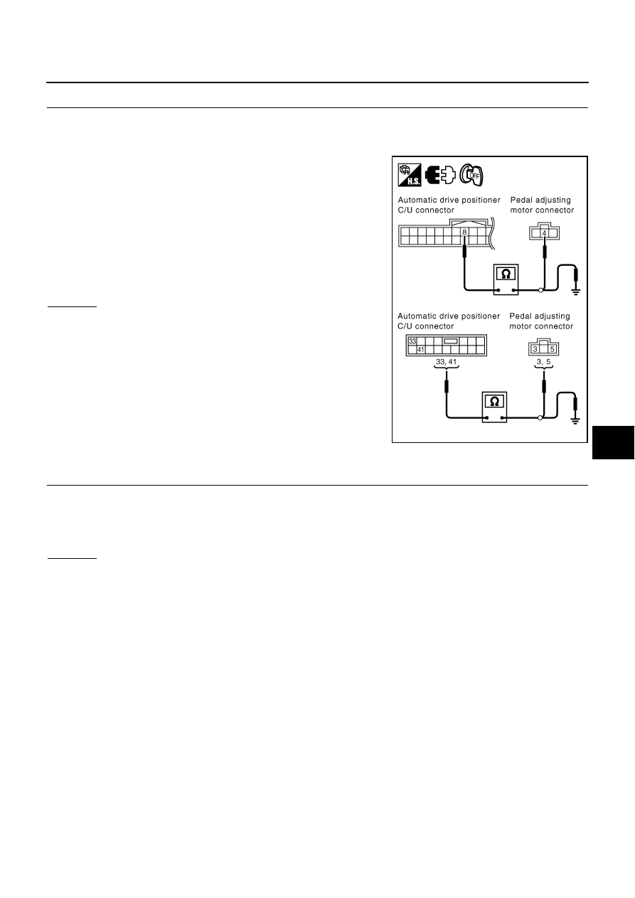
CHECK PEDAL ADJUSTING SENSOR CIRCUIT HARNESS CONTINUITY

1.

Disconnect automatic drive positioner control unit and pedal adjusting motor connector. 

2.

Check continuity between automatic drive positioner connector M19, M20 terminals 8 (P/B), 33 (W/L), 41
(Y) and pedal adjusting motor connector E114 terminals 3 (Y), 4 (P/B), 5 (W/L).

3.

Check continuity between automatic drive positioner control unit
connector E114 terminals 8 (P/B), 33 (W/L), 41 (Y) and ground.

OK or NG

OK

>> Replace pedal adjusting motor.

NG

>> Repair or replace harness between automatic drive

positioner and pedal adjusting sensor.

Mirror Sensor LH Circuit Check 

AIS003HE

1. 

CHECK DOOR MIRROR FUNCTION

Check the following items.
Operation malfunction in memory control

NOTE:
If a door mirror face position is set to an implausible angle, the set position may not be reproduced.

OK or NG

OK

>> GO TO 2.

NG

>> Repair the malfunctioning parts, and check the symptom again.

8 (P/B) – 4 (P/B)

: Continuity should exist.

33 (W/L) – 5 (W/L)

: Continuity should exist.

41 (Y) – 3 (Y)

: Continuity should exist.

8 (P/B) – Ground

: Continuity should not exist.

33 (W/L) – Ground

: Continuity should not exist.

41 (Y) – Ground

: Continuity should not exist.

PIIB4131E

SE-66

AUTOMATIC DRIVE POSITIONER

Revision: 2005 August

2005 Murano

2. 

CHECK MIRROR SENSOR CHECK

 With CONSULT–II

Check that “ON” is displayed on “MIR/SE LH R–L, MIR/SE LH U–
D" in the DATA MONITOR. 

 Without CONSULT–II

1.

Turn ignition switch ACC.

2.

Check voltage between door mirror (driver side) connector and ground.

OK or NG

OK

>> Mirror sensor LH is OK.

NG

>> GO TO 3.

3. 

CHECK HARNESS CONTINUITY 1

1.

Turn ignition switch OFF.

2.

Disconnect automatic drive positioner control unit connector and door mirror (driver side) connector.

3.

Check continuity between automatic drive positioner control unit connector M20 terminal 33 (W/L), 41 (Y)
and door mirror (driver side) connector D2 terminal 3 (W/L), 2 (Y).

4.

Check continuity between automatic drive positioner control unit
connector M20 terminal 33 (W/L), 41 (Y) and ground. 

OK or NG

OK

>> GO TO 4.

NG

>> Repair or replace harness between automatic drive

positioner control unit and door mirror (driver side).

Monitor item [OPERATION or 

UNIT]

Contents

MIR/
SEN LH R–L

“V”

Voltage output from LH door mirror sensor (LH/
RH) is displayed.

MIR/
SEN LH U–D

“V”

Voltage output from LH door mirror sensor (UP/
DOWN) is displayed.

Con-

nector

Terminals (Wire color)

Condition

Voltage (V)

(Approx,)

(+)

(–)

D2

1 (G)

Ground

When motor is 
LEFT or RIGHT 
operation 

Changes between 

3.4 (close to right edge) – 

 0.6 (close to left edge)

4 (L/Y)

When motor is 
UP or DOWN  
operation

Changes between 

3.4 (close to peak) –  

0.6 (close to valley)

PIIA0197E

PIIB3199E

33 (W/L) – 3 (W/L)

:Continuity should exist.

41 (Y) – 2 (Y)

:Continuity should exist.

33 (W/L) – Ground

:Continuity should not exist.

41 (Y) – Ground

:Continuity should not exist.

PIIB3200E

AUTOMATIC DRIVE POSITIONER

SE-67

C

D

E

F

G

H

J

K

L

M

A

B

SE

Revision: 2005 August

2005 Murano

4. 

CHECK HARNESS CONTINUITY 2

1.

Check continuity between automatic drive positioner control unit connector M19 terminal 6 (L/Y), 22 (G)
and door mirror (driver side) connector D2 terminal 1 (G), 4 (L/Y).

2.

Check continuity between automatic drive positioner control unit
connector M19 terminal 6 (L/Y), 22 (G) and ground.

OK or NG

OK

>> Replace door  mirror (driver side).

NG

>> Repair or replace harness between automatic drive

positioner control unit and door mirror (driver side).

Mirror Sensor RH Circuit Check 

AIS003HF

1. 

CHECK DOOR MIRROR FUNCTION

Check the following items.
Operation malfunction in memory control
NOTE:
If a door mirror face position is set to an implausible angle, the set position may not be reproduced.

OK or NG

OK

>> GO TO 2.

NG

>> Repair the malfunctioning parts, and check the symptom again.

2. 

CHECK MIRROR SENSOR CHECK

 With CONSULT–II

Check that “ON” is displayed on “MIR/SE RH R–L, MIR/SE RH U–
D" in the DATA MONITOR. 

 Without CONSULT–II

1.

Turn ignition switch ACC.

2.

Check voltage between door mirror (passenger side) connector and ground.

OK or NG

OK

>> Mirror sensor RH is OK.

NG

>> GO TO 3.

6 (L/Y) – 4 (L/Y)

:Continuity should exist.

22 (G) – 1 (G)

:Continuity should exist.

6 (L/Y) – Ground

:Continuity should not exist.

22 (G) – Ground

:Continuity should not exist.

PIIB3201E

Monitor item [OPERATION 

or UNIT]

Contents

MIR/
SEN RH R–L

“V”

Voltage output from RH door mirror sensor (LH/
RH) is displayed.

MIR/
SEN RH U–D

“V”

Voltage output from RH door mirror sensor (UP/
DOWN) is displayed.

Con-

nector

Terminals (Wire color)

Condition

Voltage(V)

(Approx,)

(+)

(–)

D32

1 (L)

Ground

When motor is 
LEFT or RIGHT 
operation 

Changes between 

3.4 (close to left edge) – 
 0.6 (close to right edge)

4 (R/B)

When motor is 
UP or DOWN  
operation

Changes between 

3.4 (close to peak) – 

0.6 (close to valley)

PIIA0197E

PIIB3199E

SE-68

AUTOMATIC DRIVE POSITIONER

Revision: 2005 August

2005 Murano

3. 

CHECK HARNESS CONTINUITY 1

1.

Turn ignition switch OFF.

2.

Disconnect automatic drive positioner control unit and door mirror (passenger side) connector.

3.

Check continuity between automatic drive positioner control unit connector M20 terminal 33 (W/L), 41 (Y)
and door mirror (passenger side) connector D32 terminal 3 (W/L), 2 (Y).

4.

Check continuity between automatic drive positioner control unit
connector M20 terminal 33 (W/L), 41 (Y) and ground.

OK or NG

OK

>> GO TO 4.

NG

>> Repair or replace harness between automatic drive

positioner control unit and door mirror (passenger side).

4. 

CHECK HARNESS CONTINUITY 2

1.

Check continuity between automatic drive positioner control unit
connector M19 terminal 5 (R/B), 21 (L) and door mirror (passen-
ger side) connector D32 terminal 1 (L), 4 (R/B).

2.

Check continuity between automatic drive positioner control unit
connector M19 terminal 5 (R/B), 21 (L) and ground.

OK or NG

OK

>> Replace door  mirror (passenger side).

NG

>> Repair or replace harness between automatic drive positioner control unit and door mirror (pas-

senger side).

33 (W/L) – 3 (W/L)

:Continuity should exist.

41 (Y) – 2 (Y)

:Continuity should exist.

33 (W/L) – Ground

:Continuity should not exist.

41 (Y) – Ground

:Continuity should not exist.

PIIB3200E

5 (R/B) – 4 (R/B)

:Continuity should exist.

21 (L) – 1 (L)

:Continuity should exist.

5 (R/B) – Ground

:Continuity should not exist.

21 (L) – Ground

:Continuity should not exist.

PIIB3202E

AUTOMATIC DRIVE POSITIONER

SE-69

C

D

E

F

G

H

J

K

L

M

A

B

SE

Revision: 2005 August

2005 Murano

Sliding Switch Circuit Check

AIS003H4

1. 

CHECK FUNCTION

With CONSULT-II

With “SLIDE SW-FR, SLIDE SW-RR” on the DATA MONITOR, oper-
ate the sliding switch to check ON/OFF operation.

Without CONSULT-II

1.

Turn ignition switch OFF.

2.

Check voltage between driver seat control unit connector and ground.

OK or NG

OK

>> Sliding switch circuit is OK.

NG

>> GO TO 2.

2. 

CHECK SLIDING SWITCH CIRCUIT HARNESS CONTINUITY

1.

Disconnect driver seat control unit connector and power seat switch connector.

2.

Check continuity between driver seat control unit connector
B303 terminals 11 (W/V), 26 (G/W) and power seat switch con-
nector B305 terminals 11 (W/V), 26 (G/W).

3.

Check continuity between driver seat control unit connector
B303 terminals 11 (W/V), 26 (G/W) and ground.

OK or NG

OK

>> GO TO 3.

NG

>> Repair or replace harness between driver seat control unit and power seat switch.

Monitor item [OPER-

ATION or UNIT]

Contents

SLIDE SW–
FR

"ON/

OFF"

ON / OFF status judged from the sliding switch (FR) 
signal is displayed.

SLIDE SW–
RR

"ON/

OFF"

ON / OFF status judged from the sliding switch (RR) 
signal is displayed.

PIIA0313E

Connector

Terminal

 (Wire color)

Condition

Voltage (V) 

(Approx)

(+)

(–)

B303

11 (W/V)

Ground

Sliding switch 
ON(RR operation)

0

Sliding switch OFF

Battery voltage

26 (G/W)

Sliding switch 
ON(FR operation)

0

Sliding switch OFF

Battery voltage

PIIA4577E

11 (W/V) – 11 (W/V)

: Continuity should exist.

26 (G/W) – 26 (G/W)

: Continuity should exist.

11 (W/V) – Ground

: Continuity should not exist.

26 (G/W) – Ground

: Continuity should not exist.

PIIA4578E

SE-70

AUTOMATIC DRIVE POSITIONER

Revision: 2005 August

2005 Murano

3. 

CHECK SLIDING SWITCH

Check continuity between power seat switch as follows.

OK or NG

OK

>> Check the condition of the harness and connector.

NG

>> Replace power seat switch.

Reclining Switch Check

AIS003H5

1. 

CHECK FUNCTION

 With CONSULT-II

With “RECLINING SW-FR, RECLINING SW-RR” on the DATA MON-
ITOR, operate the reclining switch to check ON/OFF operation.

 Without CONSULT-II

1.

Turn ignition switch OFF.

2.

Check voltage between driver seat control unit connector and
ground.

OK or NG

OK

>> Reclining switch circuit is OK.

NG

>> GO TO 2.

Connector

Terminal

Condition

Continuity

B305

11

32A

Sliding switch ON (RR operation)

Yes

Sliding switch OFF

No

26

Sliding switch ON (FR operation)

Yes

Sliding switch OFF

No

PIIA4579E

Monitor item [OPERA-

TION or UNIT]

Contents

RECLN SW
–FR

“ON/

OFF”

ON/OFF status judged from the reclining switch (FR) 
signal is displayed.

RECLIN S
W–RR

“ON/

OFF”

ON/OFF status judged from the reclining switch (RR) 
signal is displayed.

PIIA0313E

Connector

Terminals 

(Wire color)

Condition

Voltage (V) 

(Approx)

(+)

(–)

B303

12 (G/Y)

Ground

Reclining switch ON 
(RR operation)

0

Reclining switch 
OFF

Battery voltage

27 (L/W)

Reclining switch ON 
(FR operation)

0

Reclining switch 
OFF

Battery voltage

PIIA4580E

AUTOMATIC DRIVE POSITIONER

SE-71

C

D

E

F

G

H

J

K

L

M

A

B

SE

Revision: 2005 August

2005 Murano

2. 

CHECK RECLINING SWITCH CIRCUIT HARNESS CONTINUITY

1.

Disconnect driver seat control unit connector and power seat switch connector.

2.

Check continuity between driver seat control unit connector
B303 terminals 12 (G/Y), 27 (L/W) and power seat switch con-
nector B305 terminals 12 (G/Y), 27 (L/W). 

3.

Check continuity between driver seat control unit connector
B303 terminals 12 (G/Y), 27 (L/W) and ground.

OK or NG

OK

>> GO TO 3.

NG

>> Repair or replace harness between driver seat control unit and power seat switch.

3. 

RECLINING SWITCH CHECK

Check continuity between driver seat switch as follows.

OK or NG

OK

>> Check the condition of the harness and connector.

NG

>> Replace power seat switch.

12 (G/Y) – 12 (G/Y)

: Continuity should exist.

27 (L/W) – 27 (L/W)

: Continuity should exist.

12 (G/Y) – Ground

: Continuity should not exist.

27 (L/W) – Ground

: Continuity should not exist.

PIIA4581E

Connecter

Terminal

Condition

Continuity

B305

12

32A

Reclining switch ON (RR operation)

Yes

Reclining switch OFF

No

27

Reclining switch ON (FR operation)

Yes

Reclining switch OFF

No

PIIA4582E

SE-72

AUTOMATIC DRIVE POSITIONER

Revision: 2005 August

2005 Murano

Front Lifting Switch Circuit Check

AIS003H6

1. 

CHECK FUNCTION

 With CONSULT-II

With “LIFT FR SW-UP, LIFT FR SW-DN” on the DATA MONITOR,
operate the front lifting switch to check ON/OFF operation.

 Without CONSULT-II

1.

Turn ignition switch OFF.

2.

Check voltage between driver seat control unit connector and
ground.

OK or NG

OK

>> Front lifting switch circuit is OK.

NG

>> GO TO 2.

2. 

CHECK FROUNT RIFTING SWITCH CIRCUIT HARNESS CONTINUITY

1.

Disconnect driver seat control unit connector and power seat switch connector.

2.

Check continuity between driver seat control unit connector
B303 terminals 13 (O/B), 28 (L/R) and driver seat switch con-
nector B305 terminals 13 (O/B), 28 (L/R).

3.

Check continuity between driver seat control unit connector
B303 terminals 13 (O/B), 28 (L/R) and ground 

OK or NG

OK

>> GO TO 3.

NG

>> Repair or replace harness between driver seat control unit and power seat switch.

Monitor item [OPERA-

TION or UNIT]

Contents

LIFT FR SW–
DN

"ON/

OFF"

ON / OFF status judged from the FR lifter switch 
(DOWN) signal is displayed.

LIFT RR SW–
UP

"ON/

OFF"

ON / OFF status judged from the RR lifter switch 
(UP) signal is displayed.

PIIA0323E

Connector

Terminals 

(Wire color)

Condition

Voltage (V) 

(Approx)

(+)

(–)

B303

13 (O/B)

Ground

Front lifting switch ON
(DOWN operation)

0

Front lifting switch OFF

Battery voltage

28 (L/R)

Front lifting switch ON 
(UP operation)

0

Front lifting switch OFF

Battery voltage

PIIA4583E

13 (O/B) – 13 (O/B)

: Continuity should exist.

28 (L/R) – 28 (L/R)

: Continuity should exist.

13 (O/B) – Ground

: Continuity should not exist.

28 (L/R) – Ground

: Continuity should not exist.

PIIA4584E

AUTOMATIC DRIVE POSITIONER

SE-73

C

D

E

F

G

H

J

K

L

M

A

B

SE

Revision: 2005 August

2005 Murano

3. 

CHECK FRONT LIFTING SWITCH

Check continuity between driver seat switch as follows.

OK or NG

OK

>> Check the condition of the harness and connector.

NG

>> Replace power seat switch (driver side).

Rear Lifting Switch Circuit Check

AIS003H7

1. 

CHECK FUNCTION

 With CONSULT-II

With “LIFT RR SW-UP, LIFT RR SW-DN” on the DATA MONITOR,
operate the rear lifting switch to check ON/OFF operation.

 Without CONSULT-II

1.

Turn ignition switch OFF.

2.

Check voltage between driver seat control unit connector and
ground.

OK or NG

OK

>> Rear lifting switch circuit is OK.

NG

>> GO TO 2.

Connector

Terminals Condition

Continuity

B305

13

32A

Front lifting switch ON (DOWN operation)

Yes

Front lifting switch OFF

No

28

Front lifting switch ON (UP operation)

Yes

Front lifting switch OFF

No

PIIA4585E

Monitor item [OPERATION or 

UNIT]

Contents

LIFT RR SW–UP

“ON/OFF”

Operation (ON)/open (OFF) status judged 
from the RR lifter switch (UP) signal is dis-
played.

LIFT RR SW–DN

“ON/OFF”

Operation (ON)/open (OFF) status judged 
from the RR lifter switch (DOWN) signal is 
displayed.

PIIA0323E

Connector

Terminals

 (Wire color)

Condition

Voltage (V) 

(Approx)

(+)

(–)

B303

14 (Y/R)

Ground

Rear lifting switch ON
(DOWN operation)

0

Rear lifting switch OFF

Battery voltage

29 (W/G)

Rear lifting switch ON 
(UP operation)

0

Rear lifting switch OFF

Battery voltage

PIIA4586E

SE-74

AUTOMATIC DRIVE POSITIONER

Revision: 2005 August

2005 Murano

2. 

CHECK POWER SEAT SWITCH CIRCUIT HARNESS CONTINUITY

1.

Disconnect driver seat control unit connector and power seat switch connector.

2.

Check continuity between driver seat control unit connector
B303 terminals 14 (Y/R), 29 (W/G) and power seat switch con-
nector B305 terminals 14 (Y/R), 29 (W/G). 

3.

Check continuity between driver seat control unit connector
B303 terminals 14 (Y/R), 29 (W/G) and ground.

OK or NG

OK

>> GO TO 3.

NG

>> Repair or replace harness between driver seat control unit and power seat switch.

3. 

CHECK REAR LIFTING SWITCH

Check continuity between driver seat switch as follows.

OK or NG

OK

>> Check the condition of the harness and connector.

NG

>> Replace power seat switch.

Power Seat Switch Ground Circuit Check

AIS003H8

1. 

CHECK POWER SEAT SWITCH GROUND CIRCUIT

Check continuity between power seat switch connector B305 termi-
nal 32A (B/W) and ground.

OK or NG

OK

>> Check the condition of the harness and connector.

NG

>> Repair or replace harness between power seat switch and ground.

14 (Y/R) – 14 (Y/R)

: Continuity should exist.

29 (W/G) – 29 (W/G)

: Continuity should exist.

14 (Y/R) – Ground

: Continuity should not exist.

29 (W/G) – Ground

: Continuity should not exist.

PIIA4587E

Connector

Terminals

Condition

Continuity

B305

14

32A

Rear lifting switch ON (DOWN operation)

Yes

Rear lifting switch OFF

No

29

Rear lifting switch ON (UP operation)

Yes

Rear lifting switch OFF

No

PIIA4588E

32A (B/W) – Ground

: Continuity should exist.

PIIA4589E

AUTOMATIC DRIVE POSITIONER

SE-75

C

D

E

F

G

H

J

K

L

M

A

B

SE

Revision: 2005 August

2005 Murano

Pedal Adjusting Switch Circuit Check

AIS003H9

1. 

CHECK FUNCTION

 With CONSULT-II

With “PEDAL SW-FR, PEDAL SW-RR” on the DATA MONITOR,
operate the pedal adjusting switch to check ON/OFF operation.

 Without CONSULT-II

1.

Turn ignition switch OFF.

2.

Check voltage between driver seat control unit connector and
ground.

OK or NG

OK

>> Pedal adjusting switch circuit is OK.

NG

>> GO TO 2.

2. 

CHECK PEDAL ADJUSTING SWITCH CIRCUIT HARNESS CONTINUITY

1.

Disconnect driver seat control unit connector and pedal adjusting switch connector.

2.

Check continuity between driver seat control unit connector
B303 terminals 15 (G/R), 30 (W/L) and pedal adjusting switch
connector B306 terminals 15 (G/R), 30 (W/L). 

3.

Check continuity between driver seat control unit connector
B303 terminals 15 (G/R), 30 (W/L) and ground.

OK or NG

OK

>> GO TO 3.

NG

>> Repair or replace harness between driver seat control unit and pedal adjusting switch.

Monitor item [OPERATION or 

UNIT]

Contents

PEDAL SW–FR

“ON/OFF”

Operation (ON)/open (OFF) status 
judged from the pedal adjusting switch 
(FR) signal is displayed.

PEDAL SW–RR

“ON/OFF”

Operation (ON)/open (OFF) status 
judged from the pedal adjusting switch 
(RR) signal is displayed.

PIIA4590E

Connector

Terminals

 (Wire color)

Condition

Voltage (V) 

(Approx)

(+)

(–)

B303

15 (G/R)

Ground

Pedal adjusting switch 
ON (RR operation)

0

Pedal adjusting switch 
OFF

Battery voltage

30 (W/L)

Pedal adjusting switch 
ON (FR operation)

0

Pedal adjusting switch 
OFF

Battery voltage

PIIA4591E

15 (G/R) – 15 (G/R)

: Continuity should exist.

30 (W/L) – 30 (W/L)

: Continuity should exist.

15 (G/R) – Ground

: Continuity should not exist.

30 (W/L) – Ground

: Continuity should not exist.

PIIA4592E

SE-76

AUTOMATIC DRIVE POSITIONER

Revision: 2005 August

2005 Murano

3. 

CHECK PEDAL ADJUSTING SWITCH

Check continuity between pedal adjust switch as follows.

OK or NG

OK

>> GO TO 4.

NG

>> Replace pedal adjusting switch.

4. 

CHECK PEDAL ADJUSTING SWITCH GROUND CIRCUIT

Check continuity between pedal adjusting switch connector B306
terminal 48C (B) and ground.

OK or NG

OK

>> Check the condition of the harness and connector.

NG

>> Replace or replace harness between pedal adjusting switch and ground.

Connector

Terminals

Condition

Continu-

ity

B306

15

48C

Pedal adjusting switch ON (RR operation)

Yes

Pedal adjusting switch OFF

No

30

Pedal adjusting switch ON (FR operation)

Yes

Pedal adjusting switch OFF

No

PIIA4593E

48C (B) – Ground

: Continuity should exist.

PIIA4594E

AUTOMATIC DRIVE POSITIONER

SE-77

C

D

E

F

G

H

J

K

L

M

A

B

SE

Revision: 2005 August

2005 Murano

Door Mirror Remote Control Switch (Changeover Switch) Circuit Check

AIS003HG

1. 

CHECK FUNCTION 

With CONSULT–II

Check the operation on “MIR CHNG SW – R” or “MIR CHNG SW–
L" in the DATA MONITOR.

Without CONSULT–II

1.

Turn ignition switch ACC.

2.

Check voltage between automatic drive positioner control unit
connector and ground.

OK or NG

OK

>> Door mirror remote control switch (changeover switch) is OK.

NG

>> GO TO 2.

2. 

CHECK DOOR MIRROR REMOTE CONTROL SWITCH CIRCUIT HARNESS CONTINUITY

1.

Turn ignition switch OFF.

2.

Disconnect automatic drive positioner control unit and door mirror remote control switch connector.

3.

Check continuity between automatic drive positioner control unit
connector M19 terminal 2 (L/W), 18 (BR/Y) and door mirror
remote control switch connector M66 terminal 3 (L/W), 2 (BR/Y).

4.

Check continuity between automatic drive positioner control unit
connector M19 terminal 2 (L/W), 18 (BR/Y) and ground.

OK or NG

OK

>> GO TO 3.

NG

>> Repair or replace harness between automatic drive positioner control unit and door remote control

switch.

Monitor item [OPERATION 

or UNIT]

Contents

MIR CHNG S
W–R

“ON/OFF”

ON/OFF status judged from the door mirror remote 
control switch (switching to RIGHT) signal is dis-
played.

MIR CHNG S
W–L

“ON/OFF”

ON/OFF status judged from the door mirror remote 
control switch (switching to LEFT) signal is dis-
played.

PIIA0191E

Connector

Terminals (Wire color)

Condition

Voltage (V)

(Approx)

(+)

(-)

M19

2 (L/W)

Ground

Changeover switch 
RIGHT position

0

Changeover switch 
neutral position

5

18 (BR/Y)

Changeover switch
LEFT position

0

Changeover switch 
neutral position

5

PIIA4767E

2 (L/W) – 3 (L/W)

:Continuity should exist.

18 (BR/Y) – 2 (BR/Y)

:Continuity should exist.

2 (L/W) – Ground

:Continuity should not exist.

18 (BR/Y) – Ground

:Continuity should not exist.

PIIB4132E

SE-78

AUTOMATIC DRIVE POSITIONER

Revision: 2005 August

2005 Murano

3. 

CHECK DOOR MIRROR REMOTE CONTROL SWITCH (CHANGEOVER SWITCH) 

Check continuity between door mirror remote control switch as follows.

OK or NG

OK

>> Check the condition of the harness and the connector.

NG

>> Replace door mirror remote control switch.

Door Mirror Remote Control Switch (Mirror Switch) Circuit Check

AIS003HH

1. 

CHECK DOOR MIRROR REMOTE CONTROL SWITCH(MIRROR SWITCH) SIGNAL 

 With CONSULT–II

Check the operation on “MIR CON SW–UP/DN” and
“MIR CON SW–RH/LH” in the DATA MONITOR.

 Without CONSULT–II

1.

Turn ignition switch ACC.

2.

Check voltage between automatic drive positioner control unit
connector and ground.

OK or NG

OK

>> Door mirror remote control switch (mirror switch) circuit is OK.

NG

>> GO TO 2.

Connector

Terminals

Condition

Continuity

M66

3

13

Changeover switch RIGHT position

Yes

Changeover switch neutral position

No

2

Changeover switch LEFT position

Yes

Changeover switch neutral position

No

PIIB4133E

Monitor item [OPERATION 

or UNIT]

Contents

MIR CON SW
–UP

“ON/OFF”

ON/OFF status judged from the door mirror remote 
control switch (UP) signal is displayed.

MIR CON SW
–DN

“ON/OFF”

ON/OFF status judged from the door mirror remote 
control switch (DOWN) signal is displayed.

MIR CON SW
–RH

“ON/OFF”

ON/OFF status judged from the door mirror remote 
control switch (RIGHT) signal is displayed.

MIR CON SW
–LH

“ON/OFF”

ON/OFF status judged from the door mirror remote 
control switch (LEFT) signal s displayed.

PIIA0199E

Con-

nector

Terminals (Wire color)

Condition

Voltage (V)

(Approx)

(+)

(-)

M19

3 (Y/B)

Ground

Mirror switch UP operation

0

Mirror switch neutral position

5

4 (V/W)

Mirror switch LEFT operation

0

Mirror switch neutral position

5

19 (L/O)

Mirror switch DOWN operation

0

Mirror switch neutral position

5

20 (V)

Mirror switch RIGHT operation

0

Mirror switch neutral position

5

PIIA4771E

AUTOMATIC DRIVE POSITIONER

SE-79

C

D

E

F

G

H

J

K

L

M

A

B

SE

Revision: 2005 August

2005 Murano

2. 

CHECK HARNESS CONTINUITY

1.

Turn ignition switch OFF.

2.

Disconnect automatic drive positioner control unit and door mirror remote control switch connector.

3.

Check continuity between automatic drive positioner control unit connector M19 terminal 3 (Y/B), 4 (V/W),
19 (L/O), 20 (V) and door mirror remote control switch connector M66 terminal 4 (V), 5 (V/W), 6 (Y/B), 14
(L/O).

4.

Check continuity between automatic drive positioner control unit
connector M19 terminal 3 (Y/B), 4 (V/W), 19 (L/O), 20 (V) and
ground.

OK or NG

OK

>> GO TO 3.

NG

>> Repair or replace harness between automatic drove positioner control unit and door mirror remote

control switch.

3. 

CHECK DOOR MIRROR REMOTE CONTROL SWITCH (MIRROR SWITCH)

Check continuity between door mirror remote control switch as follows.

OK or NG

OK

>> Check the condition of the harness and connector.

NG

>> Replace door mirror remote control switch.

3 (Y/B) – 6 (Y/B)

:Continuity should exist.

4 (V/W) – 5 (V/W)

:Continuity should exist.

19 (L/O) – 14 (L/O)

:Continuity should exist.

20 (V) – 4 (V)

:Continuity should exist.

3 (Y/B) – Ground

:Continuity should not exist.

4 (V/W) – Ground

:Continuity should not exist.

19 (L/O) – Ground

:Continuity should not exist.

20 (V) – Ground

:Continuity should not exist.

PIIB4134E

Connector

Terminals

Switch condition

Continuity

M66

4

13

Mirror switch RIGHT operation

Yes

Mirror switch neutral position

No

5

Mirror switch LEFT operation

Yes

Mirror switch neutral position

No

6

Mirror switch UP operation

Yes

Mirror switch neutral position

No

14

Mirror switch DOWN operation

Yes

Mirror switch neutral position

No

PIIB4135E

SE-80

AUTOMATIC DRIVE POSITIONER

Revision: 2005 August

2005 Murano

Door Mirror Remote Control Switch Ground Circuit Check

AIS003HU

1. 

CHECK DOOR MIRROR REMOTE CONTROL SWITCH GROUND CIRCUIT

Check continuity between door mirror remote control switch connector M66 terminal 13 (B) and ground.

OK or NG

OK

>> Check the condition of the harness and the connector.

NG

>> Repair or replace harness between door mirror remote

control switch and ground.

Seat Memory Switch Circuit Check

AIS003H3

1. 

CHECK FUNCTION

 With CONSULT-II

With “SET SW,MEMORY SW1, MEMORY SW2”, “SET SW” on the
DATA MONITOR, operate the switch to check ON/OFF operation. 

 Without CONSULT-II

GO TO 2.

OK or NG

OK

>> Seat memory switch circuit is OK.

NG

>> GO TO 2.

13 (B) - Ground

: Continuity should exist.

PIIB4136E

Monitor item [OPERATION or 

UNIT]

Contents

MEMORY SW1

“ON/OFF”

ON/OFF status judged from the seat 
memory switch 1 signal is displayed.

MEMORY SW2

“ON/OFF”

ON/OFF status judged from the seat 
memory switch 2 signal is displayed.

SET SW

“ON/OFF”

ON/OFF status judged from the setting 
switch signal is displayed.

PIIA0309E


Content      ..     212      213      214      215     ..