Nissan Murano Z50 (2005 year). Manual - part 76


  Index      Manuals     Nissan Murano Z50 (2005 year) - Service and Repair Manual


Search            copyright infringement  


Content      ..     74      75      76      77     ..


Nissan Murano Z50 (2005 year). Manual - part 76


WARNING LAMPS

DI-53

C

D

E

F

G

H

I

J

L

M

A

B

DI

Revision: 2005 August

2005 Murano

3. 

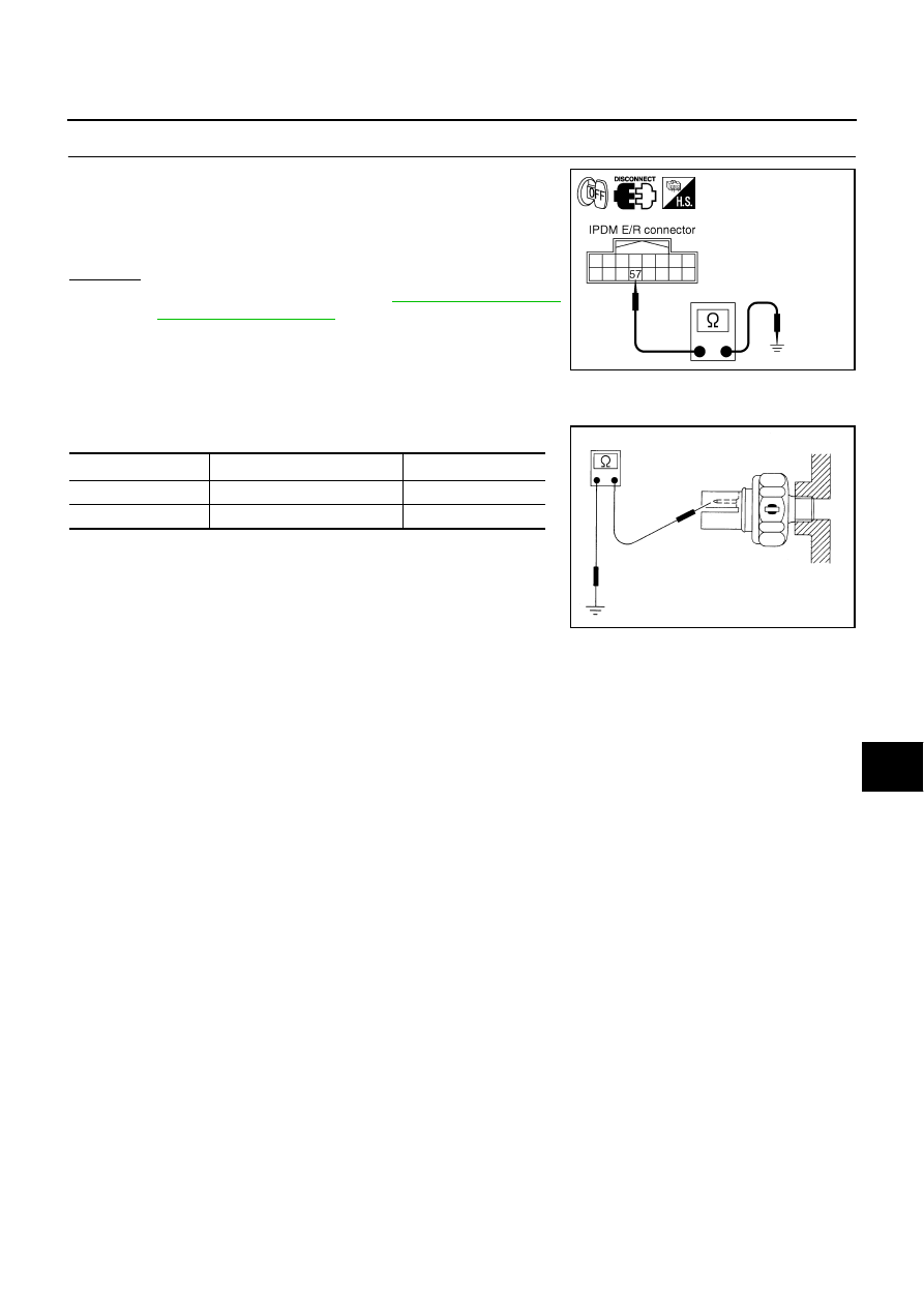
CHECK OIL PRESSURE SWITCH CIRCUIT

1.

Disconnect IPDM E/R connector.

2.

Check continuity between IPDM E/R harness connector E9 ter-
minal 57 (P/L) and ground.

OK or NG

OK

>> Replace IPDM E/R. Refer to 

PG-29, "Removal and

Installation of IPDM E/R"

 .

NG

>> Repair harness or connector.

Component Inspection

AKS00D5P

OIL PRESSURE SWITCH

Check continuity between oil pressure switch and ground.

57 (P/L) – Ground

: Continuity should not exist.

SKIA5013E

Condition

Oil pressure kPa (kg/cm

2

 , psi)

Continuity

Engine stopped

Less than 29 (0.3, 4)

Yes

Engine running

More than 29 (0.3, 4) 

No

ELF0044D

DI-54

CVT INDICATOR

Revision: 2005 August

2005 Murano

CVT INDICATOR

PFP:24820

Wiring Diagram — CVTIND —

AKS00D5Q

TKWB0103E

CVT INDICATOR

DI-55

C

D

E

F

G

H

I

J

L

M

A

B

DI

Revision: 2005 August

2005 Murano

TKWB0104E

DI-56

CVT INDICATOR

Revision: 2005 August

2005 Murano

TKWB0123E

CVT INDICATOR

DI-57

C

D

E

F

G

H

I

J

L

M

A

B

DI

Revision: 2005 August

2005 Murano

TKWB0124E

DI-58

CVT INDICATOR

Revision: 2005 August

2005 Murano

CVT Indicator Is Malfunction

AKS00D5R

1. 

CHECK SELF-DIAGNOSIS OF COMBINATION METER

Perform combination meter self-diagnosis. Refer to 

DI-14, "OPERA-

TION PROCEDURE"

 .

Are all segments displayed?

YES

>> GO TO 2.

NO

>> Replace combination meter.

2. 

CHECK SELF-DIAGNOSTIC RESULTS OF UNIFIED METER AND A/C AMP.

Select “METER A/C AMP” on CONSULT-II, and perform self-diagnosis of unified meter and A/C amp. Refer to

DI-31, "CONSULT-II Function (METER A/C AMP)"

 .

Self-diagnostic results content

No malfunction detected>> GO TO 3 (With manual mode) or GO TO 4 (Without manual mode).
Malfunction detected>> Go to 

DI-16, "Symptom Chart 2"

  in “COMBINATION METER”.

3. 

CHECK UNIFIED METER AND A/C AMP. INPUT SIGNAL

1.

Connect CONSULT-II and start engine. 

2.

Use “DATA MONITOR” of “METER A/C AMP” on CONSULT-II.
Confirm each indication on the monitor when operating the shift
lever.

OK or NG

OK

>> Replace combination meter.

NG

>> GO TO 5.

SKIA4427E

CONSULT-II display

Switch operation

Operation 

status

AT-M IND

Manual mode range

ON

Except for manual mode range

OFF

AT-M GEAR

Manual mode range (shift-up or down)

5-1

Except for manual mode range

1

P RANGE IND

P range position

ON

Except for P range position

OFF

R RANGE IND

R range position

ON

Except for R range position

OFF

N RANGE IND

N range position

ON

Except for N range position

OFF

D RANGE IND

D range position

ON

Except for D range position

OFF

SKIA6259E

CVT INDICATOR

DI-59

C

D

E

F

G

H

I

J

L

M

A

B

DI

Revision: 2005 August

2005 Murano

4. 

CHECK UNIFIED METER AND A/C AMP. INPUT SIGNAL

1.

Connect CONSULT-II and start engine. 

2.

Use “DATA MONITOR” of “METER A/C AMP” on CONSULT-II.
Confirm each indication on the monitor when operating the shift
lever.

OK or NG

OK

>> Replace combination meter.

NG

>> GO TO 5.

5. 

CHECK CVT DEVICE

Check the following.

CVT device (Manual mode switch) inspection. Refer to 

CVT-135, "DTC P0826 MANUAL MODE SWITCH

CIRCUIT"

  (With manual mode).

CVT device (Second position switch). Refer to 

CVT-181, "SECOND POSITION SWITCH"

  (Without man-

ual mode).

OK or NG

OK

>> GO TO 6.

NG

>> Repair corresponding parts.

6. 

CHECK TCM

Check TCM input/output signal. Refer to 

CVT-58, "TCM Input/Output Signal Reference Values"

 .

OK or NG

OK

>> Replace the unified meter and A/C amp. Refer to 

DI-37, "Removal and Installation of Unified

Meter and A/C Amp."

 .

NG

>> Check applicable parts, and repair or replace corresponding parts.

CONSULT-II display

Switch operation

Operation 

status

AT-M IND

OFF

AT-M GEAR

1

P RANGE IND

P range position

ON

Except for P range position

OFF

R RANGE IND

R range position

ON

Except for R range position

OFF

N RANGE IND

N range position

ON

Except for N range position

OFF

D RANGE IND

D range position

ON

Except for D range position

OFF

L RANGE IND

L range position

ON

Except for L range position

OFF

S RANGE IND

S range position

ON

Except for S range position

OFF

PKIA2499E

DI-60

WARNING CHIME

Revision: 2005 August

2005 Murano

WARNING CHIME

PFP:24814

System Description

AKS00D5S

FUNCTION

Power is supplied at all times

through 50A fusible link (letter F , located in the fuse and fusible link block)

to BCM terminal 55,

through 10A fuse [No. 18, located in the fuse block (J/B)]

to BCM terminal 42,

through 10A fuse [No. 21, located in the fuse block (J/B)] 

to key switch terminal 3 (without Intelligent Key), and

to combination meter terminal 21,

through 10A fuse [No. 22, located in the fuse block (J/B)] 

to key switch and ignition knob switch terminals 1 and 3 (with Intelligent Key),

through 10A fuse [No. 19, located in the fuse block (J/B)] 

to unified meter and A/C amp. terminal 21.

When ignition switch ON or START position, power is supplied

through 10A fuse [No. 1, located in the fuse block (J/B)]

to BCM terminal 38,

through 10A fuse [No. 12, located in the fuse block (J/B)]

to unified meter and A/C amp. terminal 22,

through 10A fuse [No. 14, located in the fuse block (J/B)]

to combination meter terminal 20.

Ground is supplied

to BCM terminal 52

through grounds E13, E26 and E28,

to unified meter and A/C amp. terminals 29 and 30

through grounds M14 and M78,

to combination meter terminals 22, 23 and 24

through grounds M14 and M78.

NOTE:
When ignition key warning chime, light warning chime, and seat belt warning chime should be conducted at
the same time, the priorities for each chime are the following.

1.

Light warning chime

2.

Ignition key warning chime

3.

Seat belt warning chime

IGNITION KEY WARNING CHIME (WITHOUT INTELLIGENT KEY)

With the key inserted into the ignition switch, and the driver's door is opened, the warning chime will sound.
Power is supplied

through key switch terminal 4

to BCM terminal 37.

Ground is supplied

through BCM terminal 62

to driver side door switch terminal 4. 

Driver side door switch terminal 5 is grounded through grounds M14 and M78.
BCM detects key inserted into the ignition switch, and sends key warning signal to unified meter and A/C amp.
with CAN communication line. Unified meter and A/C amp. sends key warning signal to combination meter
with communication line between unified meter and A/C amp. and combination meter.
When combination meter receives key warning signal, it sounds warning chime.

WARNING CHIME

DI-61

C

D

E

F

G

H

I

J

L

M

A

B

DI

Revision: 2005 August

2005 Murano

IGNITION KEY WARNING CHIME (WITH INTELLIGENT KEY)
When Mechanical Key Is Used

With the key inserted into the ignition switch, and the ignition switch LOCK or ACC, when driver's door is
opened, the warning chime will sound.
Power is supplied

through key switch and ignition knob switch terminal 4

to BCM terminal 37.

Ground is supplied

through BCM terminal 62

to driver side door switch terminal 4. 

Driver side door switch terminal 5 is grounded through grounds M14 and M78.
BCM detects key inserted into the ignition switch, and sends key warning signal to unified meter and A/C amp.
with CAN communication line. Unified meter and A/C amp. sends key warning signal to combination meter
with communication line between unified meter and A/C amp. and combination meter.
When combination meter receives key warning signal, it sounds warning chime.

When Intelligent Key Is Carried With The Driver

Intelligent Key unit detects ignition knob return is forgotten, and sends key warning signal to Intelligent Key
buzzer.
When Intelligent Key buzzer receives key warning signal, it sounds warning chime. 
Refer to 

BL-99, "WARNING CHIME FUNCTION"

 .

LIGHT WARNING CHIME

With the key removed from the ignition switch, the driver's door is  opened, and the lighting switch in 1st or 2nd
position, the warning chime will sound. [Except when headlamp battery saver control operates (for 5 minutes
after ignition switch is turned to OFF or ACC position) and headlamps do not illuminate.]
Signal is supplied

from combination switch (lighting switch) terminals 1, 2, 3, 4, 5, 6, 7, 8, 9 and 10

to BCM terminals 2, 3, 4, 5, 6, 32, 33, 34, 35 and 36.

NOTE:
BCM detected lighting switch in 1st or 2nd position, refer to 

LT-143, "Combination Switch Reading Func-

tion"

 .

Ground is supplied

through BCM terminal 62

to driver side door switch terminal 4. 

Driver side door switch terminal 5 is grounded through grounds M14 and M78.
BCM detects headlamps are illuminated, and sends light warning signal to unified meter and A/C amp. with
CAN communication line. Unified meter and A/C amp. sends light warning signal to combination meter with
communication line between unified meter and A/C amp. and combination meter.
When combination meter receives light warning signal, it sounds warning chime.

SEAT BELT WARNING CHIME

With ignition switch turned ON and seat belt unfastened [seat belt buckle switch (driver side) ON], warning
chime will sound for approximately 6 seconds.
Ground is supplied

to combination meter terminal 3

through seat belt buckle switch (driver side) terminal 50.

Seat belt buckle switch (driver side) terminal 65 is grounded through grounds B7 and B20.
Combination meter sends seat belt unfastened [seat belt buckle switch (driver side) ON] signal to unified
meter and A/C amp. with communication line between unified meter and A/C amp. and combination meter. 
BCM receives seat belt unfastened [seat belt buckle switch (driver side) ON] signal from unified meter and A/
C amp. with CAN communication line, and sends seat belt warning signal to unified meter and A/C amp. with
CAN communication line. Unified meter and A/C amp. sends seat belt warning signal to combination meter
with communication line between unified meter and A/C amp. and combination meter.
When combination meter receives seat belt warning signal, it sounds warning chime.

DI-62

WARNING CHIME

Revision: 2005 August

2005 Murano

CAN Communication System Description

AKS00D5T

CAN (Controller Area Network) is a serial communication line for real time application. It is an on-vehicle mul-
tiplex communication line with high data communication speed and excellent error detection ability. Many elec-
tronic control units are equipped onto a vehicle, and each control unit shares information and links with other
control units during operation (not independent). In CAN communication, control units are connected with 2
communication lines (CAN H line, CAN L line) allowing a high rate of information transmission with less wiring.
Each control unit transmits/receives data but selectively reads required data only.

CAN Communication Unit

AKS00D5U

Refer to 

LAN-29, "CAN Communication Unit"

  in “LAN SYSTEM”.

Component Parts and Harness Connector Location

AKS00D5V

PKIB4915E

WARNING CHIME

DI-63

C

D

E

F

G

H

I

J

L

M

A

B

DI

Revision: 2005 August

2005 Murano

Schematic

AKS00D5W

TKWB0491E

DI-64

WARNING CHIME

Revision: 2005 August

2005 Murano

Wiring Diagram — CHIME —

AKS00D5X

TKWB0492E

WARNING CHIME

DI-65

C

D

E

F

G

H

I

J

L

M

A

B

DI

Revision: 2005 August

2005 Murano

TKWB0493E

DI-66

WARNING CHIME

Revision: 2005 August

2005 Murano

TKWB0494E

WARNING CHIME

DI-67

C

D

E

F

G

H

I

J

L

M

A

B

DI

Revision: 2005 August

2005 Murano

Terminals and Reference Value for BCM

AKS00D5Y

Terminal 

No.

Wire 

color

Signal name

Measuring condition

Reference value (V)

Ignition 

switch

Operation or condition

2

R

Combination switch input 5

ON

Lighting, turn, wiper OFF
Wiper dial position 4

3

P/L

Combination switch input 4

ON

Lighting, turn, wiper OFF
Wiper dial position 4

4

R/G

Combination switch input 3

ON

Lighting, turn, wiper OFF
Wiper dial position 4

5

R/B

Combination switch input 2

ON

Lighting, turn, wiper OFF
Wiper dial position 4

6

R/W

Combination switch input 1

32

LG/B

Combination switch output 5

ON

Lighting, turn, wiper OFF
Wiper dial position 4

33

G/Y

Combination switch output 4

ON

Lighting, turn, wiper OFF
Wiper dial position 4

34

LG/R

Combination switch output 3

ON

Lighting, turn, wiper OFF
Wiper dial position 4

SKIA5291E

SKIA5292E

SKIA5291E

SKIA5292E

SKIA5291E

SKIA5292E

SKIA5291E

DI-68

WARNING CHIME

Revision: 2005 August

2005 Murano

Terminals and Reference Value for Unified Meter and A/C Amp. 

AKS00D5Z

35

G/B

Combination switch output 2

ON

Lighting, turn, wiper OFF
Wiper dial position 4

36

L/W

Combination switch output 1

37

B/R

Key switch signal

OFF

Key is removed.

Approx. 0

Key is inserted.

Approx. 12

38

R

Ignition switch ON or START 

ON

Battery voltage

39

L

CAN H

40

Y

CAN L

42

GR

Battery power supply

OFF

Battery voltage

52

B

Ground (Power)

ON

Approx. 0

55

W/B

Battery power supply (F/L)

OFF

Battery voltage

62

SB

Driver side door switch signal

OFF

ON (open)

Approx. 0

OFF (closed)

Approx. 12

Terminal 

No.

Wire 

color

Signal name

Measuring condition

Reference value (V)

Ignition 

switch

Operation or condition

SKIA5292E

Terminal 

No.

Wire 

color

Item

Measuring or condition

Reference value (V)

Ignition 

switch

Operation or condition

1

L

CAN H

OFF

9

R/B

TX communication line 
(To combination meter)

ON

11

Y

CAN L

OFF

19

R/L

RX communication line 
(From combination meter)

ON

21

Y/R

Battery power supply

OFF

Battery voltage

22

G

Ignition switch ON or START

ON

Battery voltage

29

B

Ground (power)

ON

Approx. 0

30

Ground

ON

Approx. 0

SKIA3362E

SKIA3361E


Content      ..     74      75      76      77     ..