Nissan Murano Z50 (2004 year). Manual - part 218
TROUBLE DIAGNOSIS FOR SYSTEM
TF-31
C
E
F
G
H
I
J
K
L
M
A
B
TF
Revision: 2004 November
2004 Murano
4.
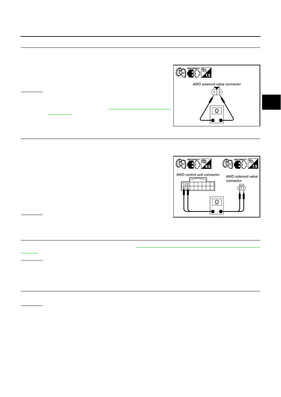
CHECK AWD SOLENOID
1.
Turn ignition switch “OFF”.
2.
Disconnect AWD solenoid valve harness connector.
3.
Check resistance between AWD solenoid valve harness con-
nector B204 terminals 1 and 2.
OK or NG
OK
>> GO TO 5.
NG
>> AWD solenoid is malfunctioning. Replace electric con-
5.
CHECK HARNESS BETWEEN AWD CONTROL UNIT AND AWD SOLENOID
1.
Turn ignition switch “OFF”.
2.
Disconnect AWD control unit harness connector and AWD solenoid valve harness connector.
3.
Check continuity between the following terminals.
–
AWD control unit harness connector E111 terminal 1 (LG) and
AWD solenoid valve harness connector B204 terminal 1 (LG).
–
AWD control unit harness connector E111 terminal 2 (L/W) and
AWD solenoid valve harness connector B204 terminal 2 (L/W).
Also check harness for short to ground and short to power.
OK or NG
OK
>> GO TO 6.
NG
>> Repair or replace damaged parts.
6.
CHECK AWD CONTROL UNIT
Check AWD control unit input/output signal. Refer to
TF-22, "AWD Control Unit Input/Output Signal Reference
OK or NG
OK
>> GO TO 7.
NG
>> Check AWD control unit pin terminals for damage or loose connection with harness connector. If
any items are damaged, repair or replace damaged parts.
7.
CHECK DTC
Perform the self-diagnosis, after driving a vehicle for a while.
OK or NG
OK
>> INSPECTION END
NG
>> Replace AWD control unit.
COMPONENT INSPECTION
1.
Turn ignition switch “OFF”.
2.
Disconnect AWD solenoid valve harness connector.
1 - 2
: Approx. 2.45
Ω
SDIA2334E
1 (LG) - 1 (LG)
: Continuity should exist.
2 (L/W) - 2 (L/W)
: Continuity should exist.
SDIA2335E