Nissan Murano Z50 (2004 year). Manual - part 219


  Index      Manuals     Nissan Murano Z50 (2004 year) - Service and Repair Manual


Search            copyright infringement  


Content      ..     217      218      219      220     ..


Nissan Murano Z50 (2004 year). Manual - part 219


TROUBLE DIAGNOSIS FOR SYMPTOMS

TF-47

C

E

F

G

H

I

J

K

L

M

A

B

TF

Revision: 2004 November

2004 Murano

2. 

CHECK INPUT SIGNAL OF TIRE DIAMETER

 With CONSULT-II

1.

Start engine.

2.

Drive at 20 km/h (12 MPH) or more for approx. 200 seconds.

3.

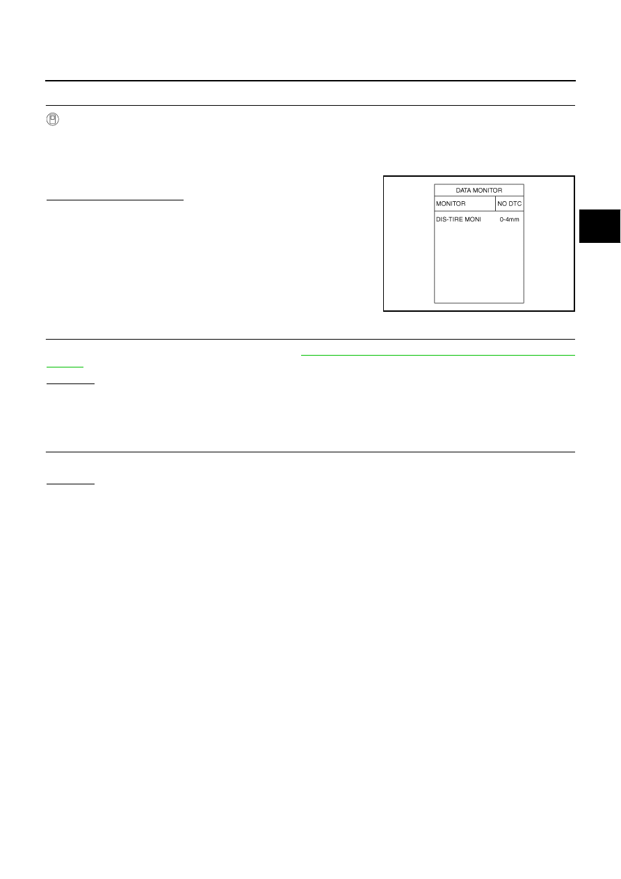
Select “DATA MONITOR” mode for “ALL MODE AWD/4WD” with CONSULT-II.

4.

Check monitor “DIS-TIRE MONI”.

Display of “DIS-TIRE MONI”

“0-4mm”>>INSPECTION END
Except for “0-4mm”>>GO TO 3.

3. 

CHECK AWD CONTROL UNIT

Check AWD control unit input/output signal. Refer to 

TF-22, "AWD Control Unit Input/Output Signal Reference

Values"

 .

OK or NG

OK

>> GO TO 4.

NG

>> Check AWD control unit pin terminals for damage or loose connection with harness connector. If

any items are damaged, repair or replace damaged parts.

4. 

SYMPTOM CHECK

Check again.

OK or NG

OK

>> INSPECTION END

NG

>> Replace AWD control unit.

SDIA1900E

TF-48

AWD CONTROL UNIT

Revision: 2004 November

2004 Murano

AWD CONTROL UNIT

PFP:41650

Removal and Installation

ADS000VY

REMOVAL

1.

Remove instrument driver lower panel. Refer to 

IP-11, "Removal and Installation"

 .

2.

Remove fuse block (J/B).

3.

Disconnect AWD control unit connector.

4.

Remove AWD control unit.

INSTALLATION

Install in the reverse order of removal.

SDIA2340E

SIDE OIL SEAL

TF-49

C

E

F

G

H

I

J

K

L

M

A

B

TF

Revision: 2004 November

2004 Murano

SIDE OIL SEAL

PFP:33142

Removal and Installation

ADS000UC

REMOVAL

NOTE:
Transaxle side oil seal is attached to transaxle assembly. Replace it when transaxle assembly is
removed from vehicle.

1.

Remove drive shaft. Refer to 

FAX-7, "FRONT DRIVE SHAFT"

 .

2.

Remove side shaft. Refer to 

FAX-7, "FRONT DRIVE SHAFT"

 .

CAUTION:

Be careful not to damage gear ring oil seal inside of transfer.

3.

Remove oil seal with a flat-bladed screwdriver.

CAUTION:

Be careful not to damage adapter case.

INSTALLATION

1.

Apply multi-purpose grease to oil seal lips. As shown in the fig-
ure, install oil seal so that it becomes flush with the case end
surface, using a drift.

CAUTION:

Do not reuse oil seal.

When installing, do not incline oil seal.

2.

Install side shaft. Refer to 

FAX-7, "FRONT DRIVE SHAFT"

 .

CAUTION:

Be careful not to damage gear ring oil seal inside of trans-
fer.

3.

Install drive shaft. Refer to 

FAX-7, "FRONT DRIVE SHAFT"

 .

4.

Check oil level. Refer to 

TF-9, "Inspection"

 .

SDIA1546E

Tool number

: KV38101700 (

)

SDIA1547E

TF-50

AIR BREATHER HOSE

Revision: 2004 November

2004 Murano

AIR BREATHER HOSE

PFP:31098

Components

ADS000WU

Removal and Installation

ADS000WV

Note the following, when removal and installation.

CAUTION:

Make sure there are no pinched or restricted areas on the air breather hose caused by bending or
winding when installing it.

Be sure to insert air breather hose into breather tube (metal con-
nector) until hose end reaches the tube's base.

Be sure to insert the paint mark of hose.

1.

Air breather hose

2.

Transfer assembly

3.

Breather tube

SDIA1859J

SCIA2663J

SDIA1824J

TRANSFER ASSEMBLY

TF-51

C

E

F

G

H

I

J

K

L

M

A

B

TF

Revision: 2004 November

2004 Murano

TRANSFER ASSEMBLY

PFP:33100

Removal and Installation

ADS000UE

COMPONENTS

REMOVAL

NOTE:
The transfer assembly itself cannot be removed from vehicle. Remove transfer assembly together with
engine assembly and transaxle assembly from vehicle. 

1.

Remove transfer assembly both with engine assembly and transaxle assembly from vehicle. Refer to 

EM-

105, "ENGINE ASSEMBLY"

 .

2.

Remove RH drive shaft. Refer to 

FAX-8, "Removal and Installation (Right Side)"

 .

3.

Remove side shaft. Refer to 

FAX-8, "Removal and Installation (Right Side)"

 .

CAUTION:

Be careful not to damage oil seal.

4.

Remove rear gusset and transfer gusset.

5.

Remove bolts fixing transaxle assembly and transfer assembly.

6.

Remove the transfer assembly from transaxle.

CAUTION:

After removing transfer assembly from transaxle, be sure to replace differential side oil seal of the
transaxle with new one. Refer to 

CVT-218, "DIFFERENTIAL SIDE OIL SEAL"

 .

INSTALLATION

Note the following, and install in the reverse order of removal.

1.

Transfer assembly

2.

Transaxle assembly

3.

Rear gusset

4.

Transfer gusset

SDIA2001E

TF-52

TRANSFER ASSEMBLY

Revision: 2004 November

2004 Murano

When installing the transfer to the transaxle, install the mounting
bolts following the standard below.

CAUTION:

When installing transfer to transaxle, be careful not to dam-
age oil seal of transaxle.

After the installation, check the oil level and oil leakage. Refer to 

TF-9, "Inspection"

 .

Bolt No.

1

2

Quantity

4

2

Bolt length “

” mm (in)

65 (2.56)

40 (1.57)

Tightening torque 
N·m (kg-m, ft-lb)

34.3 (3.5, 25)

SDIA1510E

TRANSFER ASSEMBLY

TF-53

C

E

F

G

H

I

J

K

L

M

A

B

TF

Revision: 2004 November

2004 Murano

Disassembly and Assembly

ADS000WW

COMPONENTS

1.

Pinion lock nut

2.

Companion flange

3.

Pinion sleeve oil seal

4.

Pinion rear bearing

5.

Dust cover

6.

Pinion sleeve

7.

O-ring

8.

Collapsible spacer

9.

Pinion front bearing

10. Drive pinion

11.

Pinion sleeve shim

12. Adapter case oil seal

13. Drain plug

14. Adapter case

15. Oil gutter

16. O-ring

17. Gear ring bearing adjusting shim 

(Adapter case side)

18. Gear ring bearing (Adapter case 

side)

19. Gear ring oil seal

20. Gear ring

21. Drive gear

22. Gear ring bearing (Transfer case 

side)

23. Gear ring bearing adjusting shim 

(Transfer case side)

24. Oil defense

25. Filler plug

26. Transfer case oil seal

27. Transfer case

28. Breather tube

29. Plug

PDIA0735E

TF-54

TRANSFER ASSEMBLY

Revision: 2004 November

2004 Murano

ASSEMBLY INSPECTION
Backlash

1.

Install a bolt to the companion flange.

2.

Fit a dial indicator onto the bolt.

3.

Measure the circumference backlash of the companion flange,
and make sure it satisfies the standard below.

If measured value is out of the specification, disassemble it to
check and adjust each part.

Tooth Contact

1.

Remove the pinion sleeve assembly. Refer to 

TF-58, "Pinion Sleeve Assembly"

 .

2.

Apply red lead to the drive gear.

CAUTION:

Apply red lead to both the faces of 3 to 4 gears at 4 loca-
tions evenly spaced on the drive gear.

3.

Install the pinion sleeve shims and pinion sleeve assembly.
Refer to 

TF-68, "Pinion Sleeve Assembly"

 .

4.

Remove the plug on the upper side of the transfer case.
When installing plug, apply sealant on screw part, and tighten it
at the specified torque. Refer to 

TF-53, "COMPONENTS"

 .

Use Genuine Silicone RTV or equivalent. Refer to 

GI-47,

"Recommended Chemical Products and Sealants"

 .

5.

Rotate the companion flange back and forth several times, and
check the drive pinion gear to drive gear tooth contact by view-
ing from the plug hole.

Backlash

: 0.13 - 0.19 mm (0.0051 - 0.0075 in)

SDIA1801E

SDIA1524E

SDIA1802E

TRANSFER ASSEMBLY

TF-55

C

E

F

G

H

I

J

K

L

M

A

B

TF

Revision: 2004 November

2004 Murano

6.

If tooth contact is poorly adjusted, adjust pinion height (dimen-
sion X) in the following manner.

SDIA0520E

SDIA0517E

TF-56

TRANSFER ASSEMBLY

Revision: 2004 November

2004 Murano

If the tooth contact is near the face (face contact), or near the
heal (heel contact), thin the pinion sleeve shims to move the
drive pinion closer to the drive gear.
Refer to 

TF-71, "Pinion Sleeve Shim"

 .

If the tooth contact is near the flank (flank contact), or near the
toe (toe contact), thicken the pinion sleeve shims to move the
drive pinion farther from the drive gear.
Refer to 

TF-71, "Pinion Sleeve Shim"

 .

Pinion Bearing Preload Torque

1.

Remove the pinion sleeve assembly. Refer to 

TF-58, "Pinion Sleeve Assembly"

 .

2.

Rotate the companion flange back and forth 2 to 3 times. Check for unusual noise, rotation malfunction,
and other malfunctions.

3.

Rotate the companion flange at least 20 times to check for smooth operation of the bearing.

SDIA0518E

SDIA0519E

TRANSFER ASSEMBLY

TF-57

C

E

F

G

H

I

J

K

L

M

A

B

TF

Revision: 2004 November

2004 Murano

4.

Using a preload gauge, measure the preload torque of the pin-
ion bearing.

CAUTION:

Every rotational part shall rotate smoothly with the speci-
fied gear oil.

If measured value is out of the specification, disassemble the
pinion sleeve assembly to check and adjust each part.

Total Preload Torque

1.

Measure pinion bearing preload torque (P

1

 ). Refer to 

TF-56, "Pinion Bearing Preload Torque"

 .

2.

Install the pinion sleeve shims and pinion sleeve assembly.

3.

Rotate the companion flange at least 20 times to check for smooth operation of the bearing.

4.

Using a preload gauge, measure the total preload torque.

If measured value is out of the specification, disassemble it to
check and adjust each part. If measuring the total preload
torque after the disassembly, measure it with the transfer case oil seals and gear ring oil seals
removed, then install the oil seals.

Companion Flange Runout

1.

Fit a dial indicator onto the companion flange face (inner side of
the propeller shaft mounting bolt holes).

2.

Rotate the companion flange to check for runout.

3.

Fit a test indicator to the inner side of the companion flange
(socket diameter).

4.

Rotate the companion flange to check for runout.

5.

If the runout value is outside the repair limit, follow the procedure
below to adjust.

a.

While changing the phase between companion flange and drive pinion gear by 90

°

 at a time, check runout

and determine which phase angle minimizes the runout.

b.

If the runout value is still outside of the limit after the phase has been changed, replace the companion
flange.

c.

If the runout is out of the specification after replacement of companion flange, adjust the assembly status
of the pinion bearings and drive pinion gear, or replace the pinion bearings.

Tool number

: ST3127S000 (J25765-A)

Preload torque

: 0.10 - 0.39 N·m (0.01 - 0.04 kg-m, 1 - 3 in-lb)

SDIA2076E

Pinion bearing preload torque (P1)

: 0.10 - 0.39 N·m (0.01 - 0.04 kg-m, 1 - 3 in-lb)

Tool number

: ST3127S000 (J25765-A)

Total preload torque

With all oil seals

: P

1

  + 0.16 - 0.22 N·m (0.016 - 0.023 kg-m, 1.4 - 1.9 in-lb)

Without transfer case oil seal and adapter case oil seal

: P

1

  + 0.06 - 0.12 N·m (0.006 - 0.013 kg-m, 0.6 - 1.1 in-lb)

SDIA2077E

Runout limit

: 0.1 mm (0.004 in)

Runout limit

: 0.1 mm (0.004 in)

SDIA2078E

TF-58

TRANSFER ASSEMBLY

Revision: 2004 November

2004 Murano

DISASSEMBLY
Pinion Sleeve Assembly

1.

Remove pinion sleeve mounting bolts.

2.

Using a plastic hammer, tap companion flange to remove pinion
sleeve assembly.

3.

Remove the pinion sleeve shim.

4.

Remove the pinion lock nut.

5.

Using a drift, remove drive pinion assembly from pinion sleeve
with a press.

6.

Remove companion flange.

7.

Remove the O-ring from pinion sleeve.

8.

Using a flat-bladed screwdriver, remove the pinion sleeve oil
seal.

CAUTION:

Be careful not to damage the pinion sleeve.

9.

Remove the pinion rear bearing inner race.

SDIA1803J

SDIA1861J

Tool number

: ST33220000 (J25804-01)

SDIA1806E

TFB0286D

TRANSFER ASSEMBLY

TF-59

C

E

F

G

H

I

J

K

L

M

A

B

TF

Revision: 2004 November

2004 Murano

10. Using a puller, remove the pinion rear bearing outer race.

11. Using a puller, remove the pinion front bearing outer race.

12. Remove dust cover.

13. Remove the collapsible spacer from the drive pinion.

14. Using a replacer, press the pinion front bearing inner race out of

the drive pinion.

Adapter Case

1.

Remove the adapter case mounting bolts.

Tool number

: KV381054S0 (J34286)

SDIA2079E

Tool number

: KV381054S0 (J34286)

SDIA1558E

Tool number

: ST30031000 (J22912-01)

SDIA1559E

SDIA1528E

TF-60

TRANSFER ASSEMBLY

Revision: 2004 November

2004 Murano

2.

Using a plastic hammer, tap the adapter case to remove.

3.

Remove the O-ring.

4.

Using a flat-bladed screwdriver, remove the adapter case oil
seal.

CAUTION:

Be careful not to damage the adapter case.

5.

Using a brass rod, tap the gear ring bearing adjusting shim from
the cutout on the adapter case to remove the gear ring bearing
adjusting shim and gear ring bearing outer race.

6.

Remove the oil gutter.

7.

Remove the drain plug.

Drive Gear Assembly

1.

Remove the adapter case. Refer to 

TF-59, "Adapter Case"

 .

2.

Remove the drive gear assembly from the transfer case.

SDIA1529E

SDIA1530E

SDIA1531E

SDIA1532E

TRANSFER ASSEMBLY

TF-61

C

E

F

G

H

I

J

K

L

M

A

B

TF

Revision: 2004 November

2004 Murano

3.

Using a drift and replacer, remove the gear ring bearing inner
race (adapter case side) on the gear ring.

4.

Using a drift and puller, remove the gear ring bearing inner race
(transfer case side) on the gear ring.

5.

Remove the drive gear mounting bolts.

6.

Using a plastic hammer, tap the drive gear to remove the drive
gear from the gear ring.

7.

Using a puller, remove the gear ring oil seal from the gear ring.

Transfer Case

1.

Remove the pinion sleeve assembly. Refer to 

TF-58, "Pinion Sleeve Assembly"

 .

2.

Remove the adapter case. Refer to 

TF-59, "Adapter Case"

 .

3.

Remove the drive gear assembly from the transfer case. Refer to 

TF-60, "Drive Gear Assembly"

 .

Tool number

: ST33200000 (J26082)

SDIA1560E

Tool number

: ST33061000 (J8107-2)

SDIA1561E

SDIA1807J

Tool number

: KV381054S0 (J34286)

SDIA1808E

TF-62

TRANSFER ASSEMBLY

Revision: 2004 November

2004 Murano

4.

Using a flat-bladed screwdriver, remove the transfer case oil
seal.

CAUTION:

Be careful not to damage the transfer case.

5.

Remove the oil defense.

6.

Using a brass rod, tap the gear ring bearing adjusting shim
evenly from the 2 cutouts on the transfer case to remove the
gear ring bearing adjusting shim and gear ring bearing outer
race.

7.

Remove the filler plug, plug and breather tube.

INSPECTION AFTER DISASSEMBLY
Gears

Check the gear faces and shaft for wear, cracks, damage, and seizure.

CAUTION:

If a malfunction is detected on the drive gear or drive pinion, replace the drive gear and drive pinion as
a set.

Bearings

Check for seizure, peeling, wear, corrosion, sticking/abnormal noise/roughness in hand turning, and other
damage.

CAUTION:

When replacing the bearing, always replace the inner race and outer race as a pair.

Washers and Shims

Check for seizure, damage, and unusual wear.

Oil Seals

Discard old oil seals, replace with new ones.

If wear, deterioration of adherence (sealing force of lips), or damage is detected on the lips, replace them.

TFB0297D

SDIA1533E

SDIA0536E


Content      ..     217      218      219      220     ..