Nissan Murano Z50 (2004 year). Manual - part 202
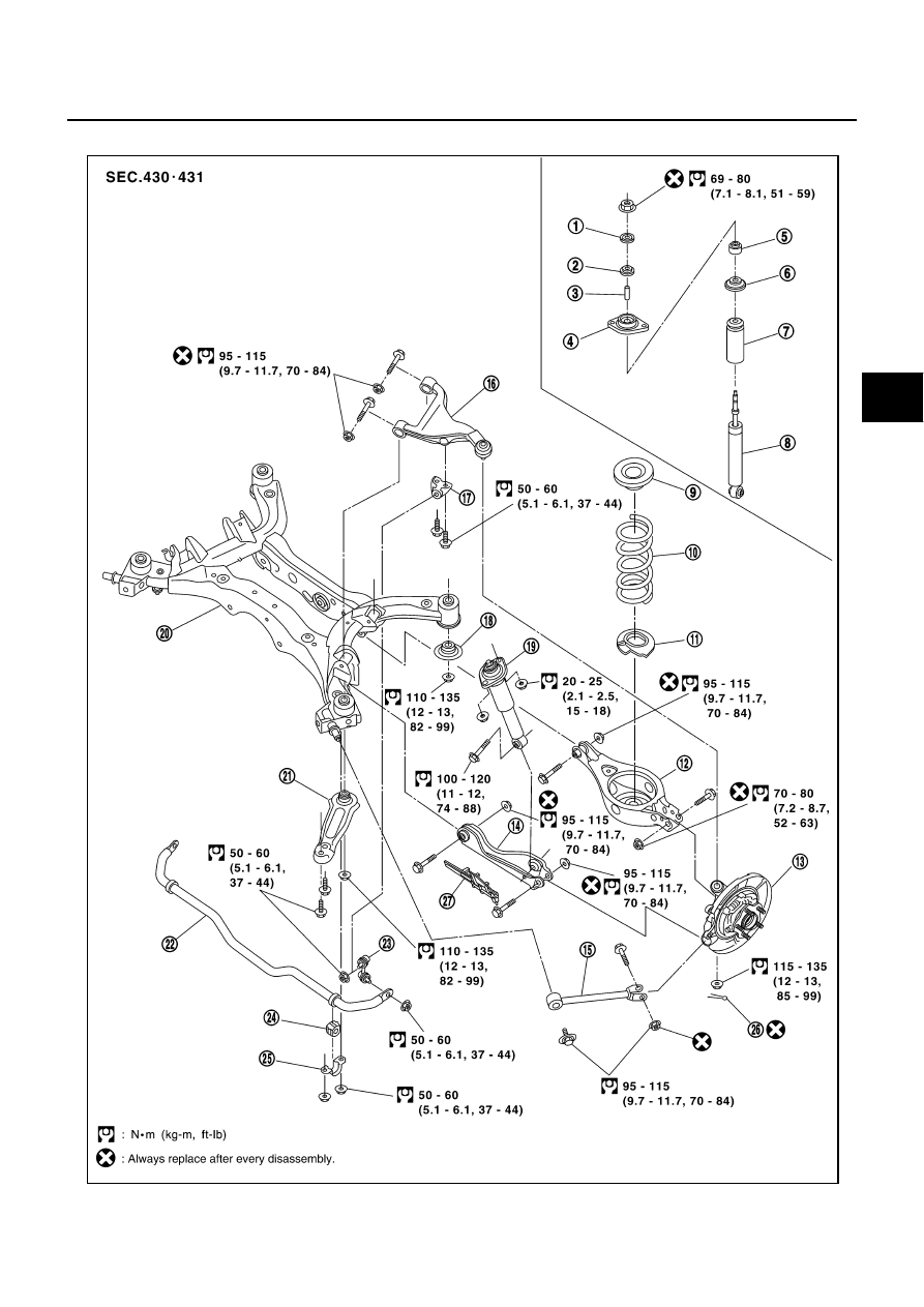
REAR SUSPENSION ASSEMBLY
RSU-7
C
D
F
G
H
I
J
K
L
M
A
B
RSU
Revision: 2004 November
2004 Murano
Components
AES000IA
SEIA0467E
|
|
|
REAR SUSPENSION ASSEMBLY RSU-7 C D F G H I J K L M A B RSU Revision: 2004 November 2004 Murano Components AES000IA SEIA0467E |