Nissan Murano Z50 (2004 year). Manual - part 200


  Index      Manuals     Nissan Murano Z50 (2004 year) - Service and Repair Manual


Search            copyright infringement  


Content      ..     198      199      200      201     ..


Nissan Murano Z50 (2004 year). Manual - part 200


PREPARATION

RFD-5

C

E

F

G

H

I

J

K

L

M

A

B

RFD

Revision: 2004 November

2004 Murano

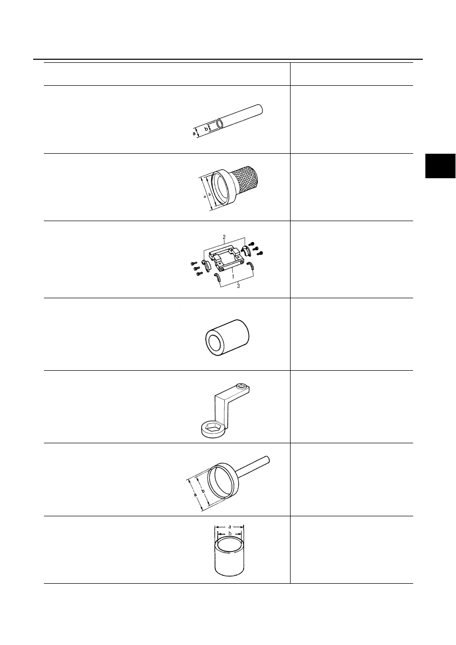
ST22350000 (J25678-01)
Drift
a: 34 mm (1.34 in) dia.
b: 28 mm (1.10 in) dia.

Installing coupling front bearing

ST33400001 (J26082)
Drift
a: 60 mm (2.36 in) dia.
b: 47 mm (1.85 in) dia.

Installing front oil seal

KV381086S1 (

 –

)  

Dummy cover set

1. KV38108610 (

 –

)

Dummy cover

2. KV38108621 (

 –

)

Dummy cap spacer

3. KV38108630 (

 –

)

Dummy cap shim

Checking backlash

Checking drive gear runout

Checking tooth contact

KV38108500   (

 –

)

Drive pinion gear socket

Measuring preload

Removing and installing drive pinion 
nut

KV38108400   (

 –

)

Pinion nut wrench

Measuring preload

ST15310000 (J25640-B)
Oil seal drift
a: 96 mm (3.78 in) dia.
b: 84 mm (3.31 in) dia.

Center oil seal installation

KV40104710  (

 –

)

Support ring
a: 76.3 mm (3.004 in) dia.
b: 67.9 mm (2.673 in) dia.

Center oil seal installation

Tool number (Kent-Moore No.)
Tool name

Description

ZZA0534D

ZZA0814D

SDIA2313E

ZZA1205D

ZZA1206D

ZZA0908D

ZZA0832D

RFD-6

PREPARATION

Revision: 2004 November

2004 Murano

Commercial Service Tools

ADS000F1

Tool name

Description

Power tool

Loosening bolts and nuts

PBIC0190E

NOISE, VIBRATION AND HARSHNESS (NVH) TROUBLESHOOTING

RFD-7

C

E

F

G

H

I

J

K

L

M

A

B

RFD

Revision: 2004 November

2004 Murano

NOISE, VIBRATION AND HARSHNESS (NVH) TROUBLESHOOTING

PFP:00003

NVH Troubleshooting Chart

ADS000K4

Use the chart below to help you find the cause of the symptom. If necessary, repair or replace these parts.

×

: Applicable

Reference page

R

e

fe

r to


RFD-1

6

, "

T

OOTH CONT

ACT

"


R

e

fe

r to


RFD-1

4

, "

P

re

-In

s

p

e

c

ti

o

n

"


R

e

fe

r to


MA

-2

2

, "

CHASSIS AND 

BODY M

A

IN

T

E

NANCE

"


NV

H

 in

 PR 

s

e

c

ti

o

n

.

NV

H

 in

 F

AX, 

RAX, FSU 

a

n

d

 RSU 

s

e

c

ti

o

n

s

.

NV

H

 in

 W

T

 s

e

c

tio

n

.

NV

H

 in

 W

T

 s

e

c

tio

n

.

NV

H

 in

 RAX 

s

e

c

ti

o

n

.

NV

H

 in

 BR 

s

e

c

ti

o

n

.

NV

H

 in

 PS 

s

e

c

ti

o

n

.

Possible cause and SUSPECTED PARTS

R

o

ugh gea

r t

o

ot

h

Im

pr

oper

 g

ear

 c

ont

act

T

oot

h sur

fa

c

es w

o

rn

In

c

o

rr

ect

 back

la

s

h

C

o

m

pani

on f

lan

ge exc

e

ssi

ve

 r

unou

t

Im

pr

oper

 g

ear

 o

il

P

R

OPE

LLER SHAFT

A

X

LE AND 

SUSPENSION

TI

R

E

S

ROAD W

H

EEL

DRIVE SHAFT

BR

AK

E

S

S

T

EERI

N

G

Symptom

DIFFERENTIAL

Noise

×

×

×

×

×

×

×

×

×

×

×

×

×

RFD-8

FRONT OIL SEAL

Revision: 2004 November

2004 Murano

FRONT OIL SEAL

PFP:38189

Removal and Installation

ADS000K5

REMOVAL

1.

Remove the propeller shaft. Refer to 

PR-4, "REAR PROPELLER SHAFT"

  .

2.

Put a mark on the end of the drive pinion corresponding to the B
position mark on the final drive companion flange.

CAUTION:

For matching mark, use paint. Never damage drive pin-
ion.

The mark on the final drive companion flange indicates
the maximum vertical runout position.

3.

Using the drive pinion flange wrench, Remove companion
flange lock nut.

4.

Using the puller, remove the companion flange.

5.

Using the side bearing outer race puller, remove front oil seal.

PDIA0034E

Tool number

: KV38108300 ( – ) 

PDIA0035E

PDIA0036E

Tool number

: ST33290001 (J34286)

PDIA0037E

FRONT OIL SEAL

RFD-9

C

E

F

G

H

I

J

K

L

M

A

B

RFD

Revision: 2004 November

2004 Murano

INSTALLATION

1.

Apply multi-purpose grease to sealing lips of oil seal. Press front
oil seal into carrier with tool.

CAUTION:

When installing the oil seal, be careful not to get it
inclined.

Discard the old oil seal. Always replace with new one.

2.

Align the matching mark of drive pinion with the matching mark
B of companion flange, then install the companion flange.

3.

Apply oil or grease on the screw part of drive pinion and the seating surface of companion flange lock nut. 

4.

Install companion flange lock nut with tool, tighten the nut to the specified torque. Refer to 

RFD-13, "Com-

ponents"

 .

CAUTION:

The companion flange lock nut is not reusable. Never reuse companion flange lock nut.

5.

Install propeller shaft. Refer to 

PR-4, "REAR PROPELLER SHAFT"

  .

Tool number

A: KV38100200 (J26233)

B: ST27861000 ( – )

PDIA0038E

PDIA0034E

Tool number

: KV38108300 ( – )

RFD-10

SIDE OIL SEAL

Revision: 2004 November

2004 Murano

SIDE OIL SEAL

PFP:38343

Removal and Installation

ADS000EI

REMOVAL

1.

Remove rear wheel sensor.Refer to 

BRC-42, "WHEEL SENSORS"

  .

2.

Remove rear axle assembly. Refer to 

RAX-5, "WHEEL HUB"

3.

Remove rear drive shaft. Refer to 

RAX-7, "REAR DRIVE SHAFT"

  .

4.

Using flat tip screwdriver as shown in the figure, remove side oil
seal.

INSTALLATION

1.

Apply multi-purpose grease to sealing lips of oil seal.

2.

Using the drift, press-fit oil seal so that its surface comes face to
face with the end surface of the case.

CAUTION:

When installing the oil seal be careful not to get it
inclined.

Discard the old oil seal. Always replace with new one.

3.

Install rear drive shaft. Refer to  

RAX-7, "REAR DRIVE SHAFT"

4.

Install rear axle assembly. Refer to 

RAX-5, "WHEEL HUB"

  .

PDIA0010E

Tool number

A: KV38100200 (J26233)

B: ST27861000 ( – ) 

PDIA0008E

REAR FINAL DRIVE ASSEMBLY

RFD-11

C

E

F

G

H

I

J

K

L

M

A

B

RFD

Revision: 2004 November

2004 Murano

REAR FINAL DRIVE ASSEMBLY

PFP:38300

Removal and Installation

ADS000EK

REMOVAL

1.

Remove rear propeller shaft. Refer to 

PR-5, "REMOVAL"

  .

2.

Remove rear stabilizer mounting bracket with power tool. Refer to 

RSU-16, "STABILIZER BAR"

  .

3.

Remove wheel sensor. Refer to 

BRC-42, "WHEEL SENSORS"

  .

4.

Remove rear drive shaft. Refer to 

RAX-7, "REAR DRIVE SHAFT"

  .

5.

Remove electric controlled coupling connector.

6.

Remove electric controlled coupling breather hose and rear final drive breather hose. 

7.

Remove canister. Refer to

EC-651, "EVAPORATIVE EMISSION SYSTEM"

  . 

8.

Set Transmission Jack to rear final drive assembly, and then
remove nuts from rear suspension member with power tool. 

CAUTION:

Do not place a transmission jack on the rear cover (alumi-
num case).

PDIA0176E

1.

Final drive mount bracket

2.

Rear propeller shaft

3.

Rear final drive assembly

PDIA0039E

RFD-12

REAR FINAL DRIVE ASSEMBLY

Revision: 2004 November

2004 Murano

9.

Remove bolt and nut of final drive mount bracket, and then
remove rear final drive assembly from vehicle with power tool.

INSTALLATION

Refer to 

RFD-13, "Components"

  about each tightening torque, and perform installation by reversing the

removal procedure with paying attention to the following matters.

Install air breather hose at the position as the figure indicates.

For installation of air breather hose, vehicle body side should be
properly inserted to member, and cup ring cover side should be
installed by aiming tip of tube to the front of the vehicle, then
metal connector should be properly force-fitted.

Install metal connector of rear cover by inserting it with aiming
blue painted marking to the rear of the vehicle.

CAUTION:

Crushing cause by bending, curved and so forth should be
avoided when installing air breather hose.

When removing final drive assembly, check quantity of oil after
the removal if oil leaks.

PDIA0040E

PDIA0180E

SDIA1745E

REAR FINAL DRIVE ASSEMBLY

RFD-13

C

E

F

G

H

I

J

K

L

M

A

B

RFD

Revision: 2004 November

2004 Murano

Components

ADS000EN

PDIA0181E

1.

Drive pinion 

2.

Pinion rear bearing 

3.

Drive pinion adjusting shim

4.

Collapsible spacer

5.

Gear carrier

6.

Pinion front bearing 

7.

Drive pinion nut

8.

Electric controlled coupling connec-
tor bracket

9.

Companion flange lock nut

10. Companion flange

11.

Front oil seal

12. Coupling cover

13. Coupling front bearing

14. Electric controlled coupling

15. Center oil seal

16.

Electric controlled coupling connec-
tor

17. Side gear

18. Pinion mate shaft

19. Side gear thrust washer

20. Pinion mate thrust washer

21. Pinion mate gear

22. Lock pin

23. Side oil seal

24. Side bearing adjusting shim

25. Side bearing

26. Differential case

27. Drive gear

28. Rear cover

29. Drain plug

30. Filler plug

31. Gasket 

RFD-14

REAR FINAL DRIVE ASSEMBLY

Revision: 2004 November

2004 Murano

Pre-Inspection

ADS000EO

TOTAL PRELOAD 

1.

Drain the oil.

2.

Remove electric controlled coupling assembly. Refer to 

RFD-19, "Removal of Electric Controlled Coupling

Assembly"

  .

3.

Rotate the drive pinion back and forth in 2 to 3 times to check for unusual noise and rotation malfunction.

4.

Rotate the drive pinion at least 20 times to check for smooth
operation of the bearing.

5.

Fit the drive pinion socket onto the drive pinion spline. Using a
preload gauge, measure the total preload.

If outside the standard, disassemble, check, and adjust each
part. Adjust the pinion bearing and side bearing preload.
Adjust the pinion bearing preload first, then adjust the side bearing preload.

Side bearing adjusting shims

Tool number

A: ST3127S000 (J25765-A)

B: KV38108500 ( – )

Total preload 

:1.33 - 2.15 N·m (0.14 - 0.21 kg-m, 12 - 19 in-lb)

Side bearing preload 

: 0.64-0.98 N·m (0.07 - 0.09 kg-m, 6 - 8 in-lb)

When the preload torque is large

On pinion bearings

: Replace the collapsible spacer.

On side bearings

: Use thinner side bearing adjusting shims.

When the preload is small

On pinion bearings

: Tighten the pinion nut.

On side bearings

: Use thicker side bearing adjusting shims.

PDIA0048E

Thickness

Part No.

Thickness 

Part No.

Thickness 

Part No.

1.85 mm (0.0728 in)
1.90 mm (0.0748 in)
1.95 mm (0.0768 in)
2.00 mm (0.0787 in)

38453 4N200
38453 4N201
38453 4N202
38453 4N203

2.05 mm (0.0807 in)
2.10 mm (0.0827 in)
2.15 mm (0.0854 in)
2.20 mm (0.0866 in)

38453 4N204
38453 4N205
38453 4N206
38453 4N207

2.25 mm (0.0886 in)
2.30 mm (0.0906 in)
2.35 mm (0.0925 in)

38453 4N208
38453 4N209
38453 4N210

REAR FINAL DRIVE ASSEMBLY

RFD-15

C

E

F

G

H

I

J

K

L

M

A

B

RFD

Revision: 2004 November

2004 Murano

DRIVE GEAR TO DRIVE PINION BACKLASH

1.

Drain the oil.

2.

Remove the rear cover. Refer to 

RFD-19, "Removal of Differential Assembly"

  .

3.

Following the procedure below, install a dummy cover set to the
gear carrier.

a.

Fit dummy cover shims to the right and left side bearing adjust-
ing shims.

b.

Temporarily tighten a dummy cover to the gear carrier.

c.

Position a dummy cover spacer to the dummy cover.

d.

Tighten rear cover mounting bolts to the specified torque. Refer to 

RFD-13, "Components"

 .

e.

Tighten dummy cover spacer mounting bolts evenly to the specified torque.

4.

Fit a dial gauge to the drive gear face to measure the backlash.

If outside the standard, change the thickness of the side bear-
ing adjusting shims.

Side bearing adjusting shims

Tool Number

: KV381086S1 ( – )

SDIA0562E

: 5.9 N·m (0.6 kg-m, 52 in-lb)

Backlash

: 0.10 - 0.15 mm (0.0039 - 0.0059 in)

PDIA0049E

When the backlash is large:

 Make the drive gear back adjusting shims thicker, and the drive gear front adjusting 
shims thinner.

When the backlash is small:

Make the drive gear back adjusting shims thinner, and the drive gear front adjusting 
shims thicker.

Thickness

Part No.

Thickness 

Part No.

Thickness

Part No.

1.85 mm (0.0728 in)
1.90 mm (0.0748 in)
1.95 mm (0.0768 in)
2.00 mm (0.0787 in)

38453 4N200
38453 4N201
38453 4N202
38453 4N203

2.05 mm (0.0807 in)
2.10 mm (0.0827 in)
2.15 mm (0.0854 in)
2.20 mm (0.0866 in)

38453 4N204
38453 4N205
38453 4N206
38453 4N207

2.25 mm (0.0886 in)
2.30 mm (0.0906 in)
2.35 mm (0.0925 in)

38453 4N208
38453 4N209
38453 4N210

RFD-16

REAR FINAL DRIVE ASSEMBLY

Revision: 2004 November

2004 Murano

DRIVE GEAR RUNOUT

1.

Drain the oil.

2.

Remove the rear cover.Refer to 

RFD-19, "Removal of Differential Assembly"

  .

3.

Attach dummy cover set. Refer to 

RFD-15, "DRIVE GEAR TO

DRIVE PINION BACKLASH"

 .

4.

Fit a dial gauge to the drive gear back face.

5.

Rotate the drive gear to measure runout.

If outside the repair limit, check drive gear assembly condi-
tion; foreign material may be caught between drive gear and
differential case, or differential case or drive gear may be
deformed, etc.

CAUTION:

Replace the drive gear and drive pinion gear as a set.

COMPANION FLANGE RUNOUT

1.

Fit a dial gauge onto the companion flange face (inner side of
the propeller shaft mounting bolt holes).

2.

Rotate the companion flange to check for runout.

3.

Fit a test indicator to the inner side of the companion flange
(socket diameter).

4.

Rotate the companion flange to check for runout.

5.

If the runout value is outside the repair limit, follow the procedure
below to adjust.

a.

Check for runout while changing the phase between companion flange and drive pinion gear by 90

°

 step,

and search for the point where the runout is the minimum.

b.

If the runout value is still outside of the limit after the phase has been changed, replace the companion
flange.

c.

If the runout value is still outside of the limit after the companion flange has been replaced, possible cause
will be an assembly malfunction of the drive pinion gear and the electronically controlled coupling, mal-
functioning coupling bearing, or malfunctioning electronically controlled coupling.

TOOTH CONTACT

1.

Drain the oil.

2.

Remove the rear cover. Refer to 

RFD-19, "Removal of Differential Assembly"

  .

3.

Attach dummy cover set. Refer to 

RFD-15, "DRIVE GEAR TO

DRIVE PINION BACKLASH"

  .

4.

Thoroughly clean drive gear and drive pinion teeth.

5.

Lightly apply a mixture of powdered ferric oxide and oil or the
equivalent. Apply it to 3 to 4 teeth of drive gear drive side.

Tool Number 

: KV381086S1 ( – )

Runout limit

: 0.05 mm (0.0020 in) or less

PDIA0050E

Runout limit

: 0.13 mm (0.0051 in)

Runout limit

: 0.13 mm (0.0051 in)

SDIA0569E

Tool Number

: KV381086S1 ( – )

PDIA0051E

REAR FINAL DRIVE ASSEMBLY

RFD-17

C

E

F

G

H

I

J

K

L

M

A

B

RFD

Revision: 2004 November

2004 Murano

6.

Rotate the drive gear back and forth in several times, check
drive pinion gear to drive gear tooth contact.

CAUTION:

Check tooth contact on drive side and reverse side.

7.

If the tooth contact is improperly adjusted, follow the procedure
below to adjust the pinion height (dimension X in the figure).

SDIA0570E

SDIA0563E

PDH0085D

RFD-18

REAR FINAL DRIVE ASSEMBLY

Revision: 2004 November

2004 Murano

Drive pinion adjusting shim

In case of face contact or heel contact, thicken the drive pin-
ion gear adjusting shims to move the drive pinion gear closer
to the drive gear.

In case of flank contact or toe contact, thin the drive pinion
gear adjusting shims to move the drive pinion gear farther
from the drive gear.

Thickness Part 

No.

Thickness Part 

No.

1.70 mm (0.0669 in)
1.73 mm (0.0681 in)
1.76 mm (0.0693 in)
1.79 mm (0.0705 in)
1.82 mm (0.0717 in)
1.85 mm (0.0728 in)
1.88 mm (0.0740 in)
1.91 mm (0.0752 in)
1.94 mm (0.0764 in)
1.97 mm (0.0776 in)

38154 4N200
38154 4N201
38154 4N202
38154 4N203
38154 4N204
38154 4N205
38154 4N206
38154 4N207
38154 4N208
38154 4N209

2.00 mm (0.0787 in)
2.03 mm (0.0799 in)

2.06 mm (0.0811 in)

2.09 mm (0.0823 in)
2.12 mm (0.0835 in)
2.15 mm (0.0846 in)
2.18 mm (0.0858 in)
2.21 mm (0.0870 in)
2.24 mm (0.0882 in)

38154 4N210

38154 4N211

38154 4N212
38154 4N213
38154 4N214
38154 4N215
38154 4N216
38154 4N217
38154 4N218

SDIA0571E

SDIA0572E

REAR FINAL DRIVE ASSEMBLY

RFD-19

C

E

F

G

H

I

J

K

L

M

A

B

RFD

Revision: 2004 November

2004 Murano

Disassembly and Assembly

ADS000EP

DISASSEMBLY
Removal of Electric Controlled Coupling Assembly

1.

Using the drive pinion flange wrench, Remove companion flange lock nut.

2.

Using the puller, remove the companion flange.

3.

Remove coupling cover.

4.

Using flat tip screwdriver, remove Front oil seal from the cou-
pling cover.

CAUTION:

Be careful not to damage the coupling cover.

5.

Remove electric controlled coupling assembly from the gear carrier.

6.

Using a puller, remove coupling front bearing from the electroni-
cally controlled coupling.

CAUTION:

When the bearing is replaced with new one, reassemble the
shim between bearing and the coupling.

Removal of Differential Assembly

1.

Using flat tip screwdriver, remove side oil seal from the gear car-
rier assembly.

CAUTION:

Be careful not to damage the gear carrier and rear cover.

2.

Remove rear cover mounting bolts.

3.

Fit a drift to the right and left side bearing adjusting shims indi-
vidually. Compress differential case assembly and side bearing
to remove gear carrier assembly and rear cover.

CAUTION:

The pressure shall be as low as possible to remove gear
carrier assembly and rear cover. The maximum pressure
shall be 10 kN (1 ton, 1.1 US ton, 1.0 Imp ton).

Tool number

: KV38108300 ( – )

PDG0213D

PDIA0177E

PDG0216D

Tool number

: KV40100610 (J26089)

PDIA0065E

RFD-20

REAR FINAL DRIVE ASSEMBLY

Revision: 2004 November

2004 Murano

NOTE:
The differential case assembly, side bearings, and adjusting shims are compressed and integrated in the
gear carrier and rear cover.

4.

Remove side bearing adjusting shims and side bearing outer race.

CAUTION:

Mark the side bearing adjusting shims so that the original mounting positions (right/left) can be
identified later.

5.

Remove drive gear mounting bolts, and remove drive gear from the differential case.

6.

Using a puller and a drift, remove side bearing inner race.

7.

Using a pin punch, pull the lock pin out of the pinion mate shaft.

8.

Remove pinion mate shaft, pinion mate gears, pinion mate
thrust washers, side gears, side gear thrust washers from the
differential case.

Removing Drive Pinion Assembly

1.

Remove Electric controlled coupling assembly. Refer to 

RFD-19, "Removal of Electric Controlled Coupling

Assembly"

  .

2.

Remove differential case assembly. Refer to 

RFD-19, "Removal of Differential Assembly"

  .

3.

Fit a drive pinion socket onto the drive pinion spline. Using a pin-
ion nut wrench, remove drive pinion nut.

4.

Remove center oil seal.

5.

Press the drive pinion gear assembly out of the gear carrier.

6.

Remove pinion front bearing inner race.

7.

Remove collapsible spacer.

Tool number

: ST33052000 ( – )

PDIA0178E

Tool number

: ST23550000 ( – )

PDIA0062E

Tool number

A: KV38108400 ( – )

B: KV38108500 ( – )

PDIA0054E

SDIA0576E


Content      ..     198      199      200      201     ..