Nissan Murano Z50 (2004 year). Manual - part 201
REAR FINAL DRIVE ASSEMBLY
RFD-21
C
E
F
G
H
I
J
K
L
M
A
B
RFD
Revision: 2004 November
2004 Murano
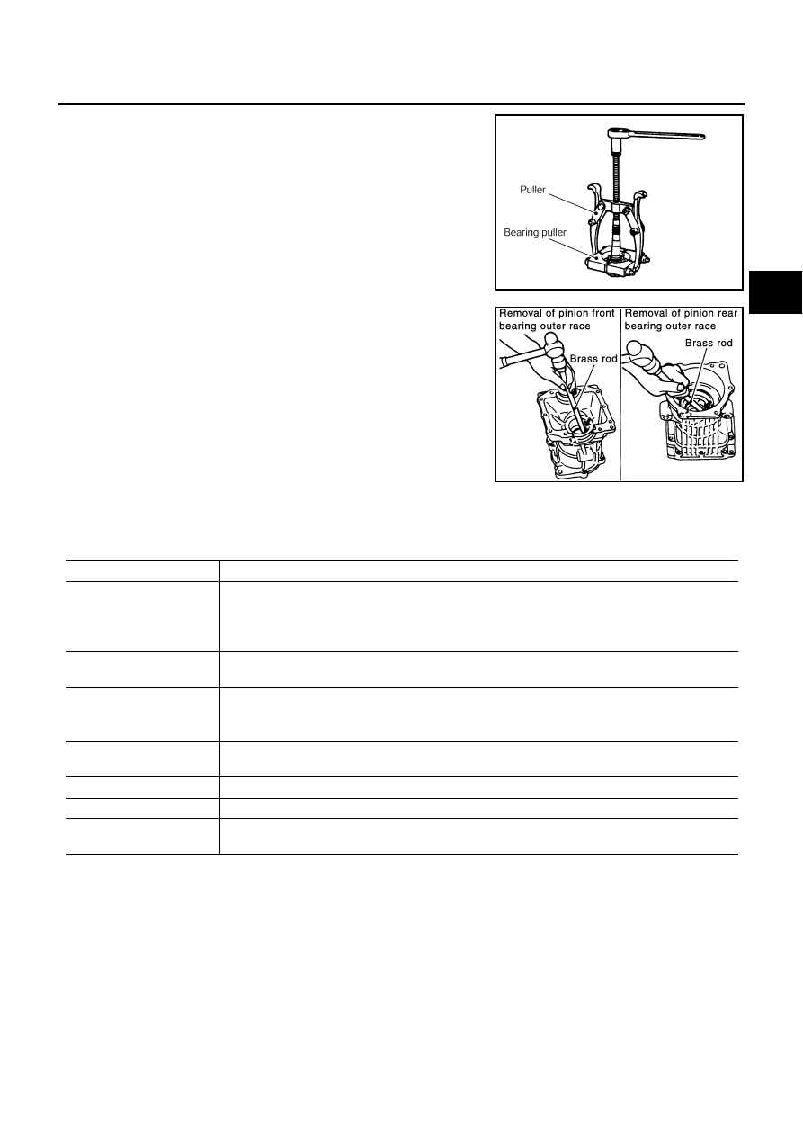
8.
Using a puller, remove pinion rear bearing inner race from the
drive pinion.
9.
Using a brass rod, tap the pinion front bearing outer race evenly
from the 2 cutouts on the gear carrier and remove pinion front
bearing outer race.
CAUTION:
Be careful not to damage the gear carrier.
10. Using a brass rod, tap the drive pinion adjusting shim evenly
from the 2 cutouts on the gear carrier and remove drive pinion
adjusting shims and pinion rear bearing outer race.
CAUTION:
Be careful not to damage the gear carrier.
Inspection
●
Clean up the disassembled parts. Then, inspect if the parts are wear or damaged. If so, follow the mea-
sures below.
PDIA0179E
SDIA0564E
Content
Measures
Hypoid gear
●
If the gear teeth do not mesh or line-up correctly, determine the cause and adjust, repair, or replace
as necessary.
●
If the gear are worn, cracked, damaged, pitted or chipped (by friction) noticeably, replace with a
new gears.
Bearing
●
If found any chipped (by friction), pitted, worn, rusted, scratched mark, or unusual noise from the
bearing, replace with a new bearing ASSY (as new set).
Side gear thrust washer and
Pinion mate thrust washer
●
Replace with a new one if found any cracks or damage on the surface of the tooth.
●
Replace with a new one if found any worn or chipped mark on the contact sides of the thrust
washer.
Side gear and Pinion mate
thrust washer
●
Replace with a new one if found that it chipped (by friction), damaged, or unusual worn.
Oil seal
●
Oil seals must be replaced with a new one whenever disassembled.
Differential case
●
Replace with a new one if found any wear or cracks on the contact sides of the Differential case.
Companion flange
●
Replace with a new one if found any chipped marks (about 0.10mm, 0.0039in) or other damage on
the contact sides of the lips of the companion flange.