Nissan Murano Z50 (2004 year). Manual - part 45


  Index      Manuals     Nissan Murano Z50 (2004 year) - Service and Repair Manual


Search            copyright infringement  


Content      ..     43      44      45      46     ..


Nissan Murano Z50 (2004 year). Manual - part 45


TROUBLE DIAGNOSIS

BRC-81

[VDC/TCS/ABS]

C

D

E

G

H

I

J

K

L

M

A

B

BRC

Revision: 2004 November

2004 Murano

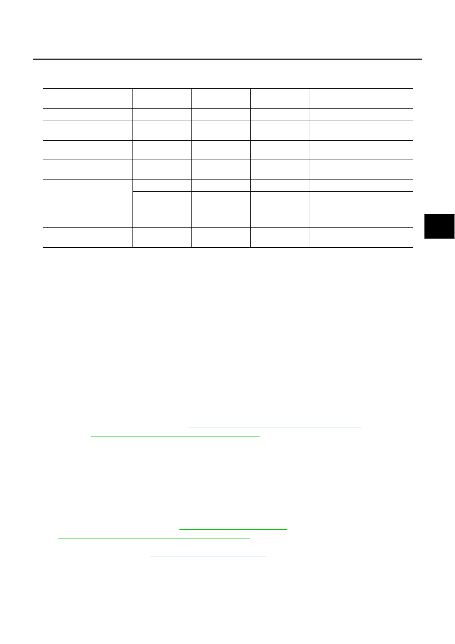
ON and OFF Timing for ABS Warning Lamp, VDC OFF Indicator Lamp, and SLIP Indicator 
Lamp

×

: ON

–: OFF

Basic Inspection

AFS00203

BASIC INSPECTION 1 BRAKE FLUID LEVEL, LEAKS, AND BRAKE PADS

1.

Check fluid level in the brake reservoir tank. If fluid level is low, refill the brake fluid.

2.

Check the brake piping and around the ABS actuator and electric unit (control unit) for leaks. If leakage or
seepage is found, check the following items.

If ABS actuator and electric unit (control unit) connection is loose, tighten the piping to the specified
torque and make sure there are no leaks.

If there is damage to the connection flare nut or ABS actuator and electric unit (control unit) screw,
replace the damaged part and re-conduct the leak inspection to make sure there are no leaks.

If there is leakage or seepage at any location other than ABS actuator and electric unit (control unit)
connection, wipe away leakage or seepage with clean cloth. Then inspect again and confirm the there
is on leakage.

If there is leakage from ABS actuator and electric unit (control unit), wipe away leakage or seepage with
clean cloth. Then inspect again. If there is leakage or seepage, replace ABS actuator and electric unit
(control unit).

CAUTION:

ABS actuator body cannot be disassembled.

3.

Check brake disc and pads. Refer to 

BR-28, "Removal and Installation of Brake Pad"

   in “Front Disc

Brake” and 

BR-34, "Removal and Installation of Brake Pad"

   in “Rear Disc Brake”.

BASIC INSPECTION 2 POWER SYSTEM TERMINAL LOOSENESS AND BATTERY INSPECTION

Make sure the battery positive cable, negative cable and ground connection are not loose. If looseness is
detected, tighten the piping to the specified torquer. In addition, check the battery voltage to make sure it has
not dropped and the altimeter is normal.

BASIC INSPECTION 3 ABS WARNING LAMP, VDC OFF INDICATOR LAMP, SLIP INDICATOR 
LAMP INSPECTION

1.

Check that ABS warning lamp, VDC OFF indicator lamp (when VDC OFF switch is OFF), and SLIP indi-
cator lamp turns ON when ignition switch is turned ON. If they do not, check the VDC OFF indicator lamp
and then VDC OFF switch. Refer to 

BRC-99, "VDC OFF SWITCH"

 . Check CAN communications. Refer

to 

BRC-97, "Inspection 13 CAN Communication System"

 . If there are no errors with VDC OFF switch and

CAN communication system, check ABS warning lamp, VDC OFF indicator lamp, SLIP indicator lamp and
combination meter. Refer to 

DI-4, "COMBINATION METERS"

 .

2.

Make sure the lamp turns OFF after ignition switch is turned ON. If the lamp does not turn OFF, conduct
self-diagnosis.

Condition

ABS warning 

lamp

VDC OFF indica-

tor lamp

SLIP indicator 

lamp

Remarks

Ignition SW OFF

After ignition SW  is turned 
ON

×

×

×

After ignition switch ON

Turns OFF  after ignition SW is 
turned ON.

VDC OFF SW is turned ON. 
(VDC/TCS function is OFF.)

×

There is an VDC/TCS/ABS
error.

×

×

×

×

×

×

There is an ABS actuator and 
electric unit (control unit) error. 
(Power or ground or system mal-
function)

When VDC/TCS is not func-
tioning normally.

×

×

BRC-82

[VDC/TCS/ABS]

TROUBLE DIAGNOSIS

Revision: 2004 November

2004 Murano

3.

With engine running, make sure VDC OFF indicator lamp turns ON and OFF when VDC OFF switch is
turned ON and OFF. If the indicator lamp status does not correspond to switch operation, check VDC OFF
switch system. Refer to 

BRC-99, "VDC OFF SWITCH"

 .

4.

Make sure ABS warning lamp, VDC OFF indicator lamp, and SLIP indicator lamp turns OFF 2 seconds
after engine is started. If ABS warning lamp, VDC OFF indicator lamp, and SLIP indicator lamp have not
turned off 10 seconds after engine has been started, conduct self-diagnosis of ABS actuator and electric
unit (control unit).

5.

After conducting self-diagnosis, be sure to erase the error memory. Refer to 

BRC-69, "CONSULT-II Func-

tions"

TROUBLE DIAGNOSIS

BRC-83

[VDC/TCS/ABS]

C

D

E

G

H

I

J

K

L

M

A

B

BRC

Revision: 2004 November

2004 Murano

Inspection 1 Wheel Sensor System

AFS00204

After using the CONSULT-II SELF-DIAG RESULTS to determine positions of malfunctioning wheel sensor,
check all areas to determine the component to be replaced.

CAUTION:

Do not measure the resistance value and also voltage between sensor terminal with tester etc.,
because e sensor is an active sensor.

Do not expand terminal of connector with a tester terminal stick, when it does the inspection with
the tester.

INSPECTION PROCEDURE

1. 

CHECK SELF-DIAGNOSIS RESULT

Check self-diagnosis results.

Is above displayed in self-diagnosis display items?

YES

>> GO TO 2.

NO

>> Inspection END

2. 

CHECK CONNECTOR

1.

Disconnect ABS actuator and electric unit (control unit) connector E24 and the malfunctioning wheel sen-
sor connector E20 (FR - LH) or E27 (FR - RH) or B202 (RR - LH), B203 (RR - RH). Check terminal to see
if it is deformed, disconnected, loose, etc., and repair or replace it if any malfunction condition is found.

2.

Reconnect connectors and check that interference with other parts has not cut wheel sensor cables, drive
at a speed of 30 km/h (19 MPH) or above for at least 1minute, and conduct self-diagnosis.

OK or NG

OK

>> Connector terminal contact is loose, damaged, open or shorted.

NG

>> GO TO 3.

Self-diagnosis results

FR RH SENSOR-1,-2

FR LH SENSOR- 1,-2

RR RH SENSOR-1,-2

RR LH SENSOR-1,- 2

ABS SENSOR

SFIA0625E

BRC-84

[VDC/TCS/ABS]

TROUBLE DIAGNOSIS

Revision: 2004 November

2004 Murano

3. 

CHECK WHEEL SENSOR HARNESS

1.

Turn ignition switch OFF and disconnect the wheel sensor con-
nector E20 (FR - LH), E27 (FR - RH), B202 (RR - LH), B203 (RR
- RH) and ABS actuator and electric unit (control unit) connector
E24.

2.

Check continuity between terminals. (Also check continuity
when steering wheel is turned right and left and when sensor
harness inside the wheel well is moved.)

OK or NG

OK

>> GO TO 4.

NG

>> Repair or replace harness and connector that have malfunction.

4. 

CHECK TIRE

Check air pressure, wear, and size.

Are air pressure, wear, and size within the standard values?

YES

>> GO TO 5.

NO

>> Adjust air pressure, or replace tire.

5. 

CHECK SENSOR AND SENSOR ROTOR

Check condition of sensor mount (for looseness, etc.).

Check surface of front sensor rotor rubber for damage.

Check rear sensor rotor for damage.

OK or NG

OK

>> GO TO 6.

NG

>> Repair or replace the malfunctioning component.

PFIA0426E

Power system

Signal system

Ground system

Wheel

ABS actuator 

and electric unit 

(control unit)

Wheel sensor

ABS actuator 

and electric unit 

(control unit)

Wheel sensor

ABS actuator 

and electric unit 

(control unit)

ABS actuator 

and electric unit 

(control unit)

(Ground)

Front RH

34 (B)

1 (B)

33 (W)

2 (W)

33 (W), 34 (B)

16 (B), 47 (B)

Front LH

45 (G)

1 (G)

46 (R)

2 (R)

45 (G), 46 (R)

Rear RH 

43 (LG)

1 (LG)

42 (V)

2 (V)

43 (LG), 42 (V)

Rear LH 

36 (L)

1 (L)

37 (P)

2 (P)

36 (L), 37 (P)

Power system

: Continuity should exist.

Signal system

: Continuity should exits.

Ground system

: Continuity should not exist.

TROUBLE DIAGNOSIS

BRC-85

[VDC/TCS/ABS]

C

D

E

G

H

I

J

K

L

M

A

B

BRC

Revision: 2004 November

2004 Murano

6. 

CHECK WHEEL SENSOR 

1.

Replace wheel sensor that resulted in malfunction by self-diagnosis.

2.

Reconnect connectors, drive vehicle at 30 km/h (19 MPH) or more for approximately 1 minute, and then
perform self-diagnosis.

Is above displayed on self-diagnosis display?

OK

>> Wheel sensor has malfunction.

NG

>>

Replace ABS actuator and electric unit (control unit).

Perform to self-diagnosis again, and make sure that the result shows “NO DTC IS DETECTED.
FURTHER TESTING MAY BE REQUIRED”.

Inspection 2 Engine System

AFS00205

INSPECTION PROCEDURE

1. 

CHECK SELF-DIAGNOSIS RESULT

Check self-diagnosis results.

Is above displayed in self-diagnosis display items?

YES

>> GO TO 2.

NO

>> Inspection END

2. 

CHECK ENGINE SYSTEM

1.

Conduct an ECM self-diagnosis and repair or replace any malfunction items. Re-conduct the ECM self-
diagnosis.

2.

Re-conduct ABS actuator and electric unit (control unit) self-diagnosis.

OK or NG

OK

>> Inspection END

NG

>> Repair or replace any malfunction items. Re-conduct self-diagnosis.

Self-diagnosis results

ENGINE SIGNAL 1

ENGINE SIGNAL 2

ENGINE SIGNAL 3

ENGINE SIGNAL 4

ENGINE SIGNAL 6

BRC-86

[VDC/TCS/ABS]

TROUBLE DIAGNOSIS

Revision: 2004 November

2004 Murano

Inspection 3 VDC/TCS/ABS Control Unit System

AFS00206

INSPECTION PROCEDURE

1. 

CHECK SELF-DIAGNOSIS RESULT

Check self-diagnosis results.

Is above displayed in self-diagnosis display items?

YES

>> Replace ABS actuator and electric unit (control unit). Re-conduct self-diagnosis.

NO

>> Inspection END

Self-diagnosis results

 CONTROLLER FAILURE

TROUBLE DIAGNOSIS

BRC-87

[VDC/TCS/ABS]

C

D

E

G

H

I

J

K

L

M

A

B

BRC

Revision: 2004 November

2004 Murano

Inspection 4 Pressure Sensor System

AFS00207

INSPECTION PROCEDURE

1. 

CHECK SELF-DIAGNOSIS RESULT

Check self-diagnosis results.

Is above displayed in self-diagnosis display items?

YES

>> GO TO 2.

NO

>> Inspection END

2. 

CHECK CONNECTOR

1.

Disconnect pressure sensor connector E23 and ABS actuator and electric unit (control unit) connector
E24, check terminals for deformation, disconnection, looseness, and so on. If there is an error, repair or
replace terminal.

2.

Reconnect connectors and Re-conduct ABS actuator and electric unit (control unit) self-diagnosis.

OK or NG

OK

>> Connector terminal contact is loose, damaged, open or shorted.

NG

>> GO TO 3.

3. 

CHECK PRESSURE SENSOR HARNESS

1.

Turn ignition switch OFF and disconnect Pressure sensor con-
nector E23 and ABS actuator and electric unit (control unit) con-
nector E24.

2.

Check continuity between ABS actuator and electric unit (control
unit) connector and pressure sensor connector.

OK or NG

OK

>> GO TO 4.

NG

>> If the open or short in harness, repair or replace harness.

Self-diagnosis results

PRESS SEN CIRCUIT

PFIA0458E

ABS actuator and electric 

unit (control unit)

Pressure sensor

Continuity

19 (W/B)

1 (W/B)

Yes

20 (LG/R)

2 (LG/R)

Yes

18 (BR/Y)

3 (BR/Y)

Yes

BRC-88

[VDC/TCS/ABS]

TROUBLE DIAGNOSIS

Revision: 2004 November

2004 Murano

4. 

PRESSURE SENSOR INSPECTION

1.

Connect pressure sensor connector E23 and ABS actuator and electric unit (control unit) connectors E24.

2.

Use “Data Monitor” to check the pressure sensor value.

OK or NG

OK

>> Inspection END

NG

>> Pressure sensor is damaged or malfunctioning, replace pressure sensor.

Condition

Data monitor display

When brake pedal is depressed.

Positive value

When brake pedal is released.

Approx. 0 bar

TROUBLE DIAGNOSIS

BRC-89

[VDC/TCS/ABS]

C

D

E

G

H

I

J

K

L

M

A

B

BRC

Revision: 2004 November

2004 Murano

Inspection 5 Steering Angle Sensor System

AFS00208

INSPECTION PROCEDURE

1. 

CHECK SELF-DIAGNOSIS RESULT

Check self-diagnosis results.

Is above displayed in self-diagnosis item?

YES

>> GO TO 2.

NO

>> Inspection END

2. 

CHECK CONNECTOR

1.

Disconnect steering angle sensor connector M33 and ABS actuator and electric unit (control unit) connec-
tor E24 and check terminals for deformation, disconnection, looseness, and so on. If there is an error,
repair or replace terminal.

2.

Reconnect connectors and Re-conduct a ABS actuator and electric unit (control unit) self-diagnosis.

OK or NG

OK

>> Connector terminal contact is loose, damaged, open or shorted.

NG

>> GO TO 3.

3. 

CHECK STEERING ANGLE SENSOR HARNESS

1.

Check CAN communication system. Refer to 

BRC-97, "Inspection 13 CAN Communication System"

 .

2.

Turn ignition switch OFF and disconnect steering angle sensor
connector M33 and ABS actuator and electric unit (control unit)
connector E24.

3.

Check continuity between ABS actuator and electric unit (control
unit) connector terminal and steering angle sensor connector
terminal.

OK or NG

OK

>> GO TO 4.

NG

>> If the open or short in harness, repair or replace harness.

4. 

CHECK STEERING WHEEL PLAY

Check steering wheel play. Refer to 

PS-8, "CHECKING STEERING WHEEL PLAY"

 .

OK or NG

OK

>> GO TO 5

NG

>> Adjustment steering wheel play.

Self-diagnosis results

ST ANGLE SEN CIRCUIT

PFIA0459E

ABS actuator and electric unit (control 

unit)

Steering angle sensor

Continuity

11 (L)

4 (L)

Yes

15 (Y)

5 (Y)

Yes

BRC-90

[VDC/TCS/ABS]

TROUBLE DIAGNOSIS

Revision: 2004 November

2004 Murano

5. 

CHECK DATA MONITOR

1.

Connect steering angle sensor and ABS actuator and electric unit (control unit) connectors.

2.

Conduct “Data Monitor” of the “STEERING ANGLE SIGNAL” to check if the status is normal.

OK or NG

OK

>> Re-conduct ABS actuator and electric unit (control unit) self-diagnosis.

NG

>> Replace spiral cable (steering angle sensor) and adjust neutral position of steering angle sensor.

Refer to 

BRC-48, "Adjustment of Steering Angle Sensor Neutral Position"

 .

Inspection 6 Yaw Rate/Side/Decel G sensor System

AFS00209

CAUTION:

Sudden turns (such as spin turns, acceleration turns), drifting, etc. May cause yaw rate/side/decel G
sensor system indicate a problem. However this is not a problem if normal operation can be resumed
after restarting engine.

INSPECTION PROCEDURE

1. 

CHECK SELF-DIAGNOSIS RESULT

Check self-diagnosis results.

CAUTION:

When on a turntable, such as at a parking structure entrance, or when on a moving object with engine
running, the VDC OFF indicator lamp might turn on and self-diagnosis using the CONSULT-II yaw rate
sensor system malfunction might be displayed, but in this case there is no problem with yaw rate/side/
decel G sensor system. As soon as the vehicle leaves the turntable or moving object, restart engine to
return the system to normal.And after doing spin turns or acceleration turns with VDC “OFF” (VDC
OFF switch “ON”),too, the results will return to a normal state by re-stating vehicle. 

Is above displayed in self-diagnosis display items?

YES

>> GO TO 2.

NO

>> Inspection END

2. 

CHECK CONNECTOR

1.

Disconnect yaw rate/side/decel G sensor connector M61 and ABS actuator and electric unit (control unit)
connector E24 and check terminals for deformation, disconnection, looseness, and so on. If there is an
error, repair or replace terminal.

2.

Reconnect connectors and re-conduct a ABS actuator and electric unit (control unit) self-diagnosis.

OK or NG

OK

>> Connector terminal contact is loose, damaged, open or shorted.

NG

>> GO TO 3.

Steering condition

Data monitor

Straight-ahead

–3.5

°

 to +3.5

°

Turn wheel to the right by 90

°

Approx. - 90

°

Turn wheel to the left by 90

°

Approx.+ 90

°

Self-diagnosis results

YAW RATE SENSOR

SIDE G-SEN CIRCUIT

G-SENSOR

TROUBLE DIAGNOSIS

BRC-91

[VDC/TCS/ABS]

C

D

E

G

H

I

J

K

L

M

A

B

BRC

Revision: 2004 November

2004 Murano

3. 

CHECK YAW RATE SENSOR/SIDE G SENSOR HARNESS

1.

Turn ignition switch OFF and disconnect yaw rate/side/decel G
sensor connector M61 and ABS actuator and electric unit (con-
trol unit) connector E24.

2.

Check continuity between ABS actuator and electric unit (control
unit) vehicle side connector and yaw rate/side/decel G sensor
vehicle side connector.

OK or NG

OK

>> GO TO 4.

NG

>> If open or short in harness, repair or replace harness.

4. 

CHECK YAW RATE SENSOR/SIDE/DECEL G SENSOR

1.

Connect yaw rate /side/decel G sensor M61 and ABS actuator and electric unit (control unit) connector
E24.

2.

Use “Data Monitor” to check if yaw rate sensor/side/decel G sensor are normal. 

OK or NG

OK

>> Perform ABS actuator and electric unit (control unit) self diagnosis again.

NG

>> Replace the malfunctioning yaw rate sensor/side/decel G sensor, and then re-conduct ABS actu-

ator and electric unit (control unit) self-diagnosis.

PFIA0460E

ABS actuator and electric unit 

(control unit)

Yaw rate/side/decel G sensor

Continuity 

6 (G/R)

3 (G/R)

Yes

24 (LG/B)

5 (P/L)

Yes

25 (W)

1 (W/G)

Yes

29 (R)

2 (R/Y)

Yes

Vehicle status

Yaw rate sensor

(Data monitor stan-

dard)

Side G sensor

(Data monitor stan-

dard)

Decel G sensor

(Data monitor stan-

dard)

When stopped

–4 to +4

°

/s

–1.1 to +1.1 m/s

2

–0.11 G to +0.11 G

Right turn

Negative value

Negative value

Left turn

Positive value

Positive value

Speed up

Negative value

Speed down

Positive value

BRC-92

[VDC/TCS/ABS]

TROUBLE DIAGNOSIS

Revision: 2004 November

2004 Murano

Inspection 7 Solenoid and VDC Change-Over Valve System

AFS0020A

INSPECTION PROCEDURE

1. 

CHECK SELF-DIAGNOSIS RESULT

Check self-diagnosis results.

Is above displayed in self-diagnosis display items?

YES

>> GO TO 2.

NO

>> Inspection END

2. 

CHECK CONNECTOR

1.

Disconnect ABS actuator and electric unit (control unit) connector E24 check terminals for deformation,
disconnection, looseness, and so on. If there is an error, repair or replace terminal.

2.

Securely reconnect connectors and conduct self-diagnosis.

OK or NG

OK

>> Connector terminal contact is loose, damaged, open or shorted.

NG

>> GO TO 3.

Self-diagnosis results

FR LH IN SOL

FR LH OUT SOL

RR RH IN SOL 

RR RH OUT SOL 

FR RH IN SOL

FR RH OUT SOL

RR LH IN SOL

RR LH OUT SOL

CV 1

CV 2

SV 1

SV 2

TROUBLE DIAGNOSIS

BRC-93

[VDC/TCS/ABS]

C

D

E

G

H

I

J

K

L

M

A

B

BRC

Revision: 2004 November

2004 Murano

3. 

CHECK SOLENOID POWER AND GROUND CIRCUIT

1.

Disconnect ABS actuator and electric unit (control unit) connector E24.

2.

Check voltage between ABS actuator and electric unit (control
unit) harness connector E24 and ground.

3.

Check resistance between ABS actuator and electric unit (con-
trol unit) harness connector E24 and ground.

OK or NG

OK

>> Perform self-diagnosis again. If the same results

appear, replace ABS actuator and electric unit (control
unit). Refer to 

BRC-106, "ACTUATOR AND ELECTRIC

UNIT (ASSEMBLY)"

 .

NG

>> Repair harness or connectors.

Inspection 8 Actuator Motor, Motor Relay, and Circuit

AFS0020B

INSPECTION PROCEDURE 

1. 

CHECK SELF-DIAGNOSIS RESULTS (1)

Check self-diagnosis results.

Is above displayed in self-diagnosis display items?

YES

>> GO TO 2.

NO

>> Inspection END.

2. 

CHECK SELF-DIAGNOSIS RESULTS (2)

1.

Disconnect ABS actuator and electric unit (control unit) connector E24. Then reconnect it securely.

2.

Perform self-diagnosis again.

Do any self-diagnosis items appear?

YES

>> GO TO 3.

NO

>> Repair or replace the applicable connector.

ABS actuator and electric 

unit (control unit)

Ground

Voltage (V)

(Approx.)

32 (R/B)

12 V

LFIA0148E

ABS actuator and electric 

unit (control unit)

Ground

Resistance 

(

)

(Approx.)

16 (B), 47 (B)

LFIA0152E

Self-diagnosis results

CONSULT-II display items

PUMP MOTOR

ACTUATOR RLY

BRC-94

[VDC/TCS/ABS]

TROUBLE DIAGNOSIS

Revision: 2004 November

2004 Murano

3. 

CHECK ABS MOTOR AND MOTOR RELAY POWER SYSTEM

1.

Disconnect ABS actuator and electric unit (control unit) connector E24.

2.

Check voltage between ABS actuator and electric unit (control
unit) connector E24 and ground.

3.

Check resistance between ABS actuator and electric unit (con-
trol unit) connector E24 and ground.

OK or NG

OK

>> Perform self-diagnosis again. If the same result

appears, replace ABS actuator and electric unit (control
unit). Refer to 

BRC-106, "ACTUATOR AND ELECTRIC

UNIT (ASSEMBLY)"

 .

NG

>> Repair harness or connectors.

Inspection 9 ABS Actuator and Electric Unit (Control Unit) Power Supply and 
Ground Circuit

AFS0020C

INSPECTION PROCEDURE

1. 

CHECK SELF-DIAGNOSIS RESULT 

Check self-diagnosis results.

Does “BATTERY VOLTAGE” appear in self-diagnosis results display?

YES

>> GO TO 2.

NO

>> Inspection END.

2. 

CHECK STARTING

1.

Disconnect ABS actuator and electric unit (control unit) connector E24. Then reconnect it securely.

2.

Perform self-diagnosis.

Do any self-diagnosis items appear?

YES

>> GO TO 3.

NO

>> Repair or replace connector.

ABS actuator and electric 

unit (control unit)

Ground

Voltage (V)

(Approx.)

1 (G/R)

12 V

LFIA0149E

ABS actuator and electric 

unit (control unit)

Ground

Resistance 

(

)

(Approx.)

16 (B)

LFIA0147E

Self-diagnosis results

CONSULT-II display items

BATTERY VOLTAGE

TROUBLE DIAGNOSIS

BRC-95

[VDC/TCS/ABS]

C

D

E

G

H

I

J

K

L

M

A

B

BRC

Revision: 2004 November

2004 Murano

3. 

CHECK ABS ACTUATOR AND ELECTRIC UNIT (CONTROL UNIT) POWER SUPPLY

1.

Disconnect ABS actuator and electric unit (control unit) connector E24.

2.

Turn ignition switch ON (but do not start engine). Check voltage
between ABS actuator and electric unit (control unit) harness
connector E24 and ground.

OK or NG

OK

>> GO TO 4.

NG

>> GO TO 5

4. 

CHECK ABS ACTUATOR AND ELECTRIC UNIT (CONTROL UNIT) GROUND CIRCUITS

Check ABS actuator and electric unit (control unit) ground circuits.

OK or NG

OK

>> Perform ABS actuator and electric unit (control unit) self-

diagnosis again.

NG

>> Repair harness or connectors.

5. 

CHECK ABS ACTUATOR AND ELECTRIC UNIT (CONTROL UNIT) POWER SYSTEM

1.

Disconnect ABS actuator and electric unit (control unit) connector E24. 

2.

Check continuity between battery positive terminal and ABS
actuator and electric unit (control unit) connector E24.

OK or NG

YES

>> Check for malfunction conditions in battery (terminal

looseness, low voltage, etc.) and alternator.

NO

>> Repair harness or connectors.

Inspection 10 Stop Lamp Switch System

AFS0020D

INSPECTION PROCEDURE

1. 

CHECK SELF-DIAGNOSIS RESULT

Check self-diagnosis results.

Is above displayed in self-diagnosis display items?

YES

>> GO TO 2.

NO

>> Inspection END

ABS actuator and electric 

unit (control unit)

Ground

Voltage (V)

(Approx.)

4 (GR)

12 V

LFIA0151E

ABS actuator and electric 

unit (control unit)

Ground

Continuity

16 (B), 47 (B)

Yes

LFIA0152E

ABS actuator and electric 

unit (control unit)

Battery 

positive 

terminal

Continuity

4 (G/R)

Yes

PFIA0461E

Self-diagnosis results

STOP LAMP SW

BRC-96

[VDC/TCS/ABS]

TROUBLE DIAGNOSIS

Revision: 2004 November

2004 Murano

2. 

CHECK CONNECTOR

1.

Disconnect the stop lamp switch connector E116 and ABS actuator and electric unit (control unit) connec-
tor E24 and check terminals for deformation, disconnection, looseness, and so on. If any malfunction is
found, repair or replace terminal.

2.

Securely reconnect connectors.

3.

Start engine.

4.

Repeat pumping brake pedal carefully several times, then perform self-diagnosis again.

OK or NG

OK

>> Connector terminal contact is loose, damaged, open or shorted.

NG

>> GO TO 3.

3. 

CHECK STOP LAMP SWITCH CIRCUIT

1.

Turn ignition switch OFF and disconnect stop lamp switch con-
nector E116 and ABS actuator and electric unit (control unit)
connector E24.

2.

Check continuity between stop lamp switch harness connector
E116 and ABS actuator and electric unit (control unit) harness
connector E24. 

OK or NG

OK

>> Connect connectors and conduct a ABS actuator and electric unit (control unit) self-diagnosis.

NG

>> Open or short in harness. Repair or replace harness.

Inspection 11 Brake Fluid Level Sensor System

AFS0020E

INSPECTION PROCEDURE

1. 

CHECK SELF-DIAGNOSIS RESULT

1.

Check the brake reservoir tank fluid level. If the level is low, add brake fluid.

2.

Erase self-diagnosis results and check self-diagnosis results.

Is above displayed in self-diagnosis display items?

YES

>> GO TO 2.

NO

>> Inspection END

2. 

CHECK CONNECTOR

1.

Disconnect the brake fluid level sensor connector E21 and ABS actuator and electric unit (control unit)
connector E24 and check terminal for deformation, disconnection, looseness, and so on. If there is any
malfunction condition, repair or replace terminal.

2.

Securely reconnect connectors and Re-conduct self-diagnosis.

OK or NG

OK

>> Connector terminal contact is loose, damaged, open or shorted.

NG

>> GO TO 3.

ABS actuator and electric 

unit (control unit)

Stop lamp 

switch 

Continuity

41 (R/G)

2 (R/G)

Yes

LFIA0150E

Self-diagnosis results

BR FLUID LEVEL LOW


Content      ..     43      44      45      46     ..