Nissan Murano Z50 (2004 year). Manual - part 30
REMOTE KEYLESS ENTRY SYSTEM
BL-73
C
D
E
F
G
H
J
K
L
M
A
B
BL
Revision: 2004 November
2004 Murano
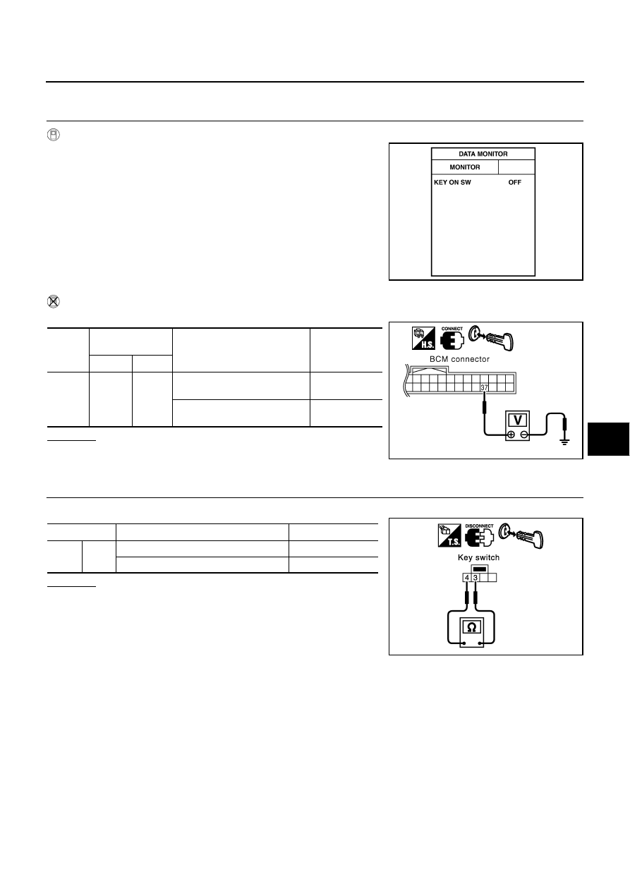
Check Key Switch
AIS003Y8
1.
CHECK KEY SWITCH INPUT SIGNAL
With CONSULT-II
Check ignition key switch “IGN ON SW” in “DATA MONITOR” mode
with CONSULT-II.
●
When key is inserted in ignition key cylinder
●
When key is removed from ignition key cylinder
Without CONSULT-II
Check voltage between BCM connector and ground.
OK or NG
OK
>> Key switch circuit is OK.
NG
>> GO TO 2.
2.
CHECK KEY SWITCH
Check continuity between key switch connector M28 terminals 3 and 4.
OK or NG
OK
>> GO TO 3.
NG
>> Replace key switch.
KEY ON SW
: ON
KEY ON SW
: OFF
PIIA6470E
Con-
nector
Terminal
(Wire color)
Condition
Voltage [V]
(Approx.)
(+)
(–)
M34
37 (B/R)
Ground
Key is removed from ignition key
cylinder.
0
Key is inserted in ignition key
cylinder.
Battery voltage
PIIA6471E
Terminal
Condition
Continuity
3
4
Key is removed from ignition key cylinder.
No
Key is inserted in ignition key cylinder.
Yes
PIIA3044E