Nissan Murano Z50 (2004 year). Manual - part 29
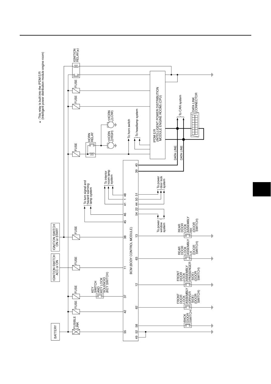
REMOTE KEYLESS ENTRY SYSTEM
BL-57
C
D
E
F
G
H
J
K
L
M
A
B
BL
Revision: 2004 November
2004 Murano
Schematic
AIS002FI
TIWA0491E
|
|
|
REMOTE KEYLESS ENTRY SYSTEM BL-57 C D E F G H J K L M A B BL Revision: 2004 November 2004 Murano Schematic AIS002FI TIWA0491E |