Nissan Murano Z50 (2003 year). Manual - part 262
SC-14
STARTING SYSTEM
Revision; 2004 April
2003 Murano
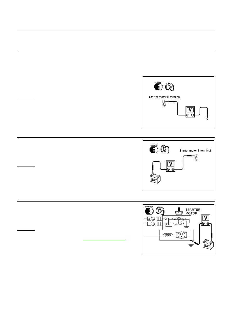
DIAGNOSTIC PROCEDURE 1
Check “B” Terminal Circuit
1.
CHECK POWER SUPPLY FOR STARTER MOTOR “B” TERMINAL
1.
Remove fuel pump fuse.
2.
Crank or start the engine (where possible) until the fuel pressure is released.
3.
Turn ignition switch OFF.
4.
Make sure the starter motor B terminal F38 terminal 2 (B/R) connection is clean and tight.
5.
Check voltage between starter motor B terminal F38 terminal 2
(B/R) and ground using a digital circuit tester.
OK or NG
OK
>> GO TO 2.
NG
>> Check harness between the battery and the starter
motor for open circuit.
2.
CHECK BATTERY HARNESS CONNECTION (VOLTAGE DROP TEST)
Check voltage between starter motor B terminal F38 terminal 2 (B/R)
and battery positive terminal using a digital circuit tester.
OK or NG
OK
>> GO TO 3.
NG
>> Check harness between the battery and the starter
motor for poor continuity.
3.
CHECK STARTER MOTOR GROUND CIRCUIT (VOLTAGE DROP TEST)
Check voltage between starter motor case and battery negative ter-
minal using a digital circuit tester.
OK or NG
OK
>> Starter motor “B” terminal circuit is OK. Further inspec-
tion necessary. Refer to
NG
>> Check the starter motor case and ground for poor conti-
nuity.
Battery voltage should exist.
PKIA2369E
When the ignition switch is in START position,
Voltage: Less than 0.5V
PKIA2370E
When the ignition switch is in START position,
Voltage: Less than 0.2V
PKIA2786E