Nissan Murano Z50 (2003 year). Manual - part 129
CAMSHAFT
EM-73
C
D
E
F
G
H
I
J
K
L
M
A
EM
Revision; 2004 April
2003 Murano
Inner Diameter of Camshaft Bracket
●
Tighten camshaft bracket bolt with specified torque.
●
Using inside micrometer, measure inner diameter “A” of cam-
shaft bracket.
Calculation of Camshaft Journal Clearance
●
(Journal clearance) = (inner diameter of camshaft bracket) –
(outer diameter of camshaft journal).
●
When out of the limit, replace either or both camshaft and cylinder head.
NOTICE:
Inner diameter of camshaft bracket is manufactured together with cylinder head. Replace the whole cylin-
der head assembly.
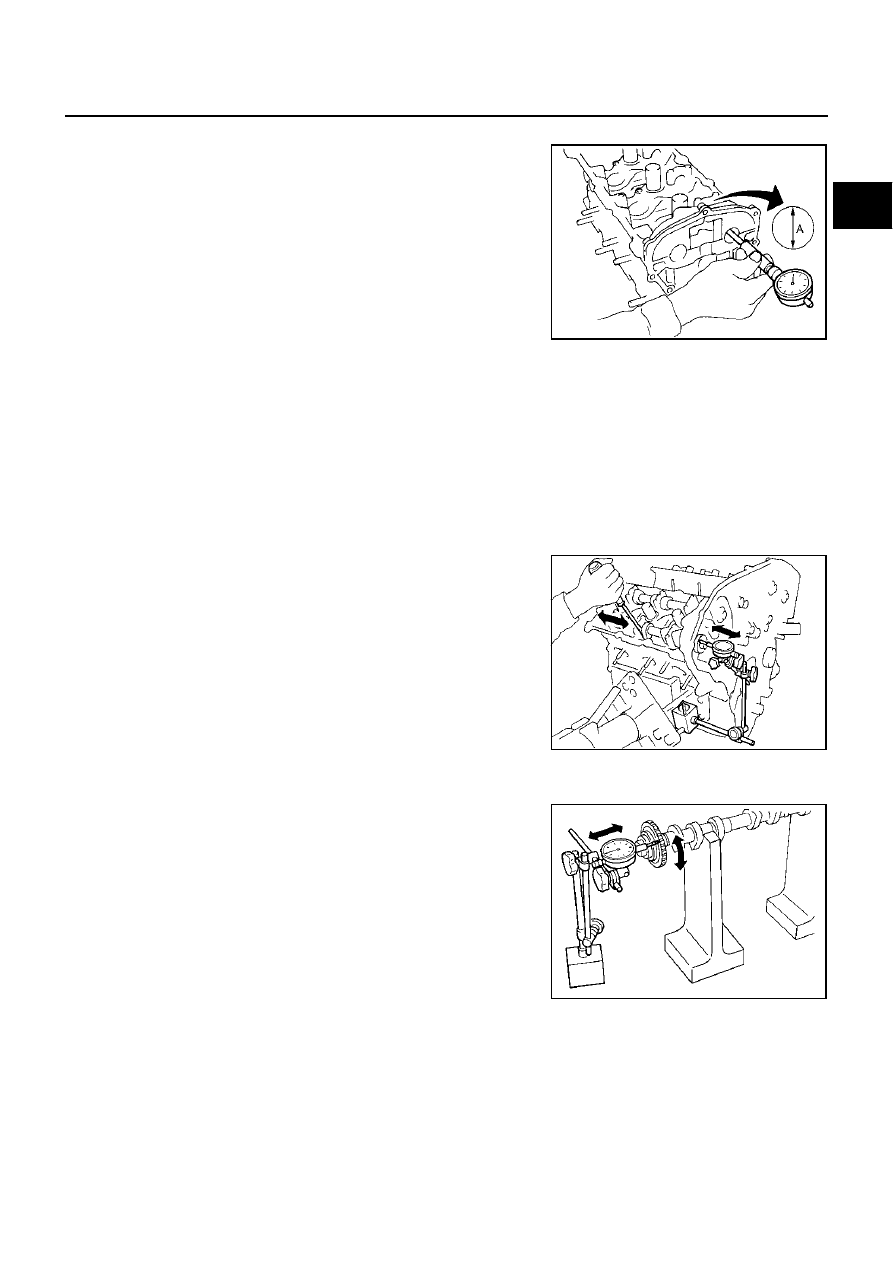
Camshaft End Play
●
Install dial gauge in thrust direction on front end of camshaft.
Measure end play of dial gauge when camshaft is moved for-
ward/backward (in direction to axis).
●
When out of the limit, replace with new camshaft and measure
again.
●
When out of the limit again, replace with new cylinder head.
Camshaft Sprocket Runout
1.
Put V block on precise flat bed, and support No. 2 and No. 4 journal of camshaft.
2.
Using dial gauge and measure camshaft sprocket runout. (Total
indicator reading)
●
If it exceeds the limit, replace camshaft sprocket.
Standard inner diameter:
No. 1
: 26.000 - 26.021 mm (1.0236 - 1.0244 in)
No. 2, 3, 4
: 23.500 - 23.521 mm (0.9252 - 0.9260 in)
Standard:
No. 1
: 0.045 - 0.086 mm (0.0018 - 0.0034 in)
No. 2, 3, 4
: 0.035 - 0.076 mm (0.0014 - 0.0030 in)
Limit
: 0.15 mm (0.0059 in)
PBIC1645E
Standard
: 0.115 - 0.188 mm (0.0045 - 0.0074 in)
Limit
: 0.24 mm (0.0094 in)
SEM864E
Limit
: 0.15 mm (0.0059 in)
PBIC0930E