Nissan Murano Z50 (2003 year). Manual - part 127


  Index      Manuals     Nissan Murano Z50 (2003 year) - Service and Repair Manual


Search            copyright infringement  


Content      ..     125      126      127      128     ..


Nissan Murano Z50 (2003 year). Manual - part 127


FUEL INJECTOR AND FUEL TUBE

EM-41

C

D

E

F

G

H

I

J

K

L

M

A

EM

Revision; 2004 April

2003 Murano

When installing O-ring, be careful not to scratch it with tool or fingernails. Also be careful not
to twist or stretch O-ring. If O-ring was stretched while it was being attached, do not insert it
quickly into fuel tube.

Insert fuel damper straight into fuel tube.

Tighten mounting bolts evenly in turn.

After tightening mounting bolts, make sure that there is no gap between flange and fuel tube.

2.

Install O-rings to fuel injector paying attention to the items below.

CAUTION:

Upper and lower O-ring are different. Be careful not to confuse them.

Handle O-ring with bare hands. Never wear gloves.

Lubricate O-ring with new engine oil.

Do not clean O-ring with solvent.

Make sure that O-ring and its mating part are free of foreign material.

When installing O-ring, be careful not to scratch it with tool or fingernails. Also be careful not to
twist or stretch O-ring. If O-ring was stretched while it was being attached, do not insert it
quickly into fuel tube.

Insert O-ring straight into fuel tube. Do not decenter or twist it.

3.

Install fuel injector to fuel tube with the following procedure.
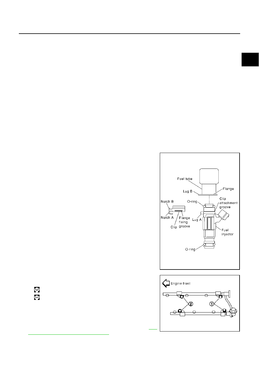
a.

Insert clip into clip mounting groove on fuel injector.

Insert clip so that lug “A” of fuel injector matches notch “A” of
the clip.

CAUTION:

Do not reuse clip. Replace it with a new one.

Be careful to keep clip from interfering with O-ring. If
interference occurs, replace O-ring.

b.

Insert fuel injector into fuel tube with clip attached.

Insert it while matching it to the axial center.

Insert fuel injector so that lug “B” of fuel tube matches notch
“B” of the clip.

Make sure that fuel tube flange is securely fixed in flange fix-
ing groove on clip.

c.

Make sure that installation is complete by checking that fuel
injector does not rotate or come off.

4.

Tighten mounting bolts in two steps in numerical order shown in
figure.

CAUTION:

Be careful not to let tip of injector nozzle come in contact
with other parts.

5.

Connect fuel injector harness.

6.

Install intake manifold collector (upper and lower). Refer to 

EM-

16, "INTAKE MANIFOLD COLLECTOR"

 .

Fuel tube side

: Black

Nozzle side

: Green

PBIC1021E

 1st step : 9.3 - 10.8 N·m (0.95 - 1.1 kg-m, 6.9 - 7.9 ft-lb)

 2nd step : 20.6 - 26.5 N·m (2.1 - 2.7 kg-m, 16 - 19 ft-lb)

SEC999C

EM-42

FUEL INJECTOR AND FUEL TUBE

Revision; 2004 April

2003 Murano

7.

Connect quick connector between fuel feed hose (with damper)
and centralized under-floor piping connection with the following
procedure:

a.

Check the connection for damage and foreign materials.

b.

Align the quick connector with the tube, then insert the connec-
tor straight into the tube until a click is heard.

c.

After connecting the quick connector, use the following method
to make sure it is full connected.

Visually confirm that the two retainer tabs are connected to
the connector.

Pull the tube and the connector to make sure they are
securely connected.

d.

Install quick connector cap to quick connector connection.

Install quick connector cap with arrow on surface facing in
direction of quick connector.

CAUTION:

If cap cannot be installed smoothly, quick connector may
have not been installed correctly. Check connection again.

8.

Install in the reverse order of removal after this step.

INSPECTION AFTER INSTALLATION

Check on Fuel Leakage

1.

Turn ignition switch ON (with engine stopped). With fuel pressure applied to fuel piping, check for fuel
leakage at connection points.

2.

Start engine. With engine speed increased, check again for fuel leakage at connection points.

NOTE:
Use mirrors for checking at points out of clear sight.

CAUTION:

Do not touch the engine immediately after stopped, as engine becomes extremely hot.

PBIC1180E

PBIC1181E

ROCKER COVER

EM-43

C

D

E

F

G

H

I

J

K

L

M

A

EM

Revision; 2004 April

2003 Murano

ROCKER COVER

PFP:13264

Removal and Installation

ABS0034R

REMOVAL

1.

Remove the intake manifold collector (upper and lower) with power tool. Refer to 

EM-16, "INTAKE MANI-

FOLD COLLECTOR"

 .

2.

Remove the ignition coil. Refer to 

EM-35, "IGNITION COIL"

 .

3.

Remove PCV hoses from rocker covers.

1.

PCV hose

2.

Oil filler cap

3.

Rocker cover (RH bank)

4.

PCV valve

5.

O-ring

6.

Rocker cover gasket

7.

Rocker cover (LH bank)

PBIC1183E

EM-44

ROCKER COVER

Revision; 2004 April

2003 Murano

4.

Loosen bolts in the reverse order shown in the figure (with
power tool).

INSTALLATION

1.

Apply liquid gasket of 3.0 mm (0.12 in) diameter to position
shown in the figure (both edges of No.1 camshaft bracket) (on
both banks).

First, apply it to engine longitudinal direction [5.0 mm (0.197
in) + 5.0 mm (0.197 in) side in figure].

Use Genuine Thread Sealant or equivalent. Refer to 

GI-46,

"RECOMMENDED CHEMICAL PRODUCTS AND SEAL-
ANTS"

 .

2.

Install rocker cover.

Check if rocker cover gasket is dropped from installation groove of rocker cover.

PBIC1184E

PBIC0786E

ROCKER COVER

EM-45

C

D

E

F

G

H

I

J

K

L

M

A

EM

Revision; 2004 April

2003 Murano

3.

Tighten bolts two steps separately in order numbers in illustra-
tion.

4.

Install PCV hose.

Insert PCV hose by 25 to 30 mm (0.98 to 1.18 in) from connector end.

When installing, be careful not to twist or come in contact with other parts.

Install PCV hose between right and left rocker covers with its identification paint facing upward (right
rocker cover side).

5.

Install in the reverse order of removal after this step.

 1st step

: 0.96 - 2.96 N·m (0.10 - 0.30 kg-m, 9 - 26 in-lb)

 2nd step

: 7.33 - 9.33 N·m (0.75 - 0.95 kg-m, 65 - 82 in-lb)

PBIC1184E

EM-46

FRONT TIMING CHAIN CASE

Revision; 2004 April

2003 Murano

FRONT TIMING CHAIN CASE

PFP:13599

Removal and Installation

ABS0032M

NOTE:

This section describes removal/installation procedure of front timing chain case and timing chain related
parts without removing upper oil pan on vehicle.

When upper oil pan needs to be removed or installed, or when rear timing chain case is removed or
installed, remove lower and upper oil pans first. Then remove front timing chain case, timing chain related
parts, and rear timing chain case in this order, and install in reverse order of removal. Refer to 

EM-54,

"TIMING CHAIN"

 .

Refer to 

EM-54, "TIMING CHAIN"

  for component parts location.

REMOVAL

1.

Place vehicle onto lift.

2.

Disconnect battery ground cable.

3.

Remove engine cover. Refer to 

EM-16, "INTAKE MANIFOLD COLLECTOR"

 .

4.

Remove radiator cover grilles, air duct (inlet), air cleaner case assembly and air duct. Refer to 

EM-14,

"AIR CLEANER AND AIR DUCT"

 .

5.

Remove RH and LH rocker covers. Refer to 

EM-43, "ROCKER COVER"

 .

NOTE:
When only primary timing chain is removed, rocker cover does not need to be removed.

6.

Remove splash guard (RH).

7.

Drain engine coolant from radiator. Refer to 

CO-8, "Changing Engine Coolant"

 .

8.

Drain engine oil. Refer to 

LU-8, "Changing Engine Oil"

 .

9.

Remove engine harnesses.

10. Remove A/C compressor from bracket with piping connected, and temporarily secure it aside. Refer to

ATC-152, "Removal and Installation of Compressor"

 .

11. Remove power steering oil pump from bracket with piping connected, and temporarily secure it aside.

Refer to 

PS-28, "Removal and Installation"

 .

12. Remove power steering oil pump bracket. Refer to 

PS-28, "Removal and Installation"

 .

13. Remove alternator. Refer to 

SC-27, "Removal and Installation"

 .

14. Remove idler pulley and bracket. Refer to 

EM-54, "TIMING CHAIN"

 .

15. Obtain compression TDC of No.1 cylinder as follows:

NOTE:
When timing chain is not removed/installed, this step is not
required.

a.

Rotate crankshaft pulley clockwise to align timing mark (grooved
line without color) with timing indicator.

b.

Check that intake and exhaust cam noses on No. 1 cylinder
(engine front side of RH bank) are located as shown.

If not, turn the crankshaft one revolution (360

°

) and align as

shown.

NOTE:
When only primary timing chain is removed, rocker cover does
not need to be removed. To confirm that No. 1 cylinder is at its
compression TDC, remove front timing chain case first. Then
check mating marks on camshaft sprockets. Refer to 

EM-54,

"TIMING CHAIN"

  .

SEM918G

SEM418G

FRONT TIMING CHAIN CASE

EM-47

C

D

E

F

G

H

I

J

K

L

M

A

EM

Revision; 2004 April

2003 Murano

16. Loosen crankshaft pulley bolt. (At this time remove oil pan rear

cover plate and set a suitable tool to ring gear so that crankshaft
cannot rotate.)

CAUTION:

Exercise care not to damage signal plate.

17. Remove crankshaft pulley with a suitable puller.

18. Remove lower oil pan. Refer to 

EM-26, "OIL PAN AND OIL

STRAINER"

 .

19. Loosen bolts in reverse order shown in figure, and remove

installation bolts at the front of upper oil pan.

20. Install lower oil pan temporarily.

21. Support the lower oil pan bottom with a transmission jack.

Perform following operations with engine front-side supported
with jack.

22. Remove the RH and LH intake valve timing control covers.

Loosen bolts in reverse order as shown.

Use seal cutter [special service tool: KV10111100 (J37228)]
or an equivalent tool to cut liquid gasket for removal.

CAUTION:

Shaft is internally jointed with intake camshaft sprocket
center hole. When removing, keep it horizontal until it is
completely disconnected.

SEM965F

SEM915E

PBIC1637E

SEM728G

EM-48

FRONT TIMING CHAIN CASE

Revision; 2004 April

2003 Murano

23. Remove right side engine mounting, mounting bracket and nuts. Refer to 

EM-95, "ENGINE ASSEMBLY"

 .

24. Raise engine front-side with jack. (This secures workspace to remove front timing chain case.)

25. Remove front timing chain case.

a.

Loosen mounting bolts in reverse order as shown.

b.

Insert the appropriate size tool into the notch at the top of the
front timing chain case as shown (1).

c.

Pry off the case by moving the tool as shown (2).

Use seal cutter [special service tool: KV10111100 (J37228)]
or an equivalent tool to cut liquid gasket for removal. 

CAUTION:

Do not use screwdrivers or something similar.

After removal, handle it carefully so it does not tilt, cant,
or warp under a load.

26. Remove water pump cover and chain tensioner cover from front timing chain case. 

Use seal cutter [special service tool: KV10111100 (J37228)] or an equivalent tool to cut liquid gasket for
removal. 

27. Remove the front oil seal from the front timing chain case using

a suitable tool.

Use screwdriver for removal.

Exercise care not to damage front timing chain case.

28. Remove timing chain and related parts. Refer to 

EM-54, "TIMING CHAIN"

  starting from step 11. (Disre-

gard the procedures for removing front timing chain case and upper oil pan.)

29. Remove residual gasket from front timing chain case and liquid gasket mating surface.

CAUTION:

Be careful not to allow gasket fragments to enter oil pan.

INSTALLATION

1.

Install timing chain and related parts. Refer to 

EM-54, "TIMING CHAIN"

 .

SEM730G

SEM156F

EMQ0032D

FRONT TIMING CHAIN CASE

EM-49

C

D

E

F

G

H

I

J

K

L

M

A

EM

Revision; 2004 April

2003 Murano

2.

Hammer dowel pins (right and left) into front timing chain case
up to a point close to taper in order to shorten protrusion length.

3.

Install the front oil seal on the front timing chain case. Apply
new engine oil to the oil seal edges.

Install it so that each seal lip is oriented as shown in figure. 

Using a suitable drift, press-fit oil seal until it becomes flush
with timing chain case end face.

Make sure the garter spring is in position and seal lip is not
inverted.

4.

Install the water pump cover and the chain tensioner cover to
front cover.

Apply RTV Silicone Sealant or equivalent. Refer to 

GI-46,

"RECOMMENDED CHEMICAL PRODUCTS AND SEAL-
ANTS"

 .

PBIC1101E

SEM715A

PBIC0790E

SEM744GA

EM-50

FRONT TIMING CHAIN CASE

Revision; 2004 April

2003 Murano

5.

Install front timing chain case as follows:

a.

Apply liquid gasket to front timing chain case back side as
shown.

Apply RTV Silicone Sealant or equivalent. Refer to 

GI-46,

"RECOMMENDED CHEMICAL PRODUCTS AND SEAL-
ANTS"

 .

b.

Install oil pan gasket.

Apply RTV Silicone Sealant or equivalent. Refer to 

GI-46,

"RECOMMENDED CHEMICAL PRODUCTS AND SEAL-
ANTS"

  .

Align notch of front timing chain case with protrusion of oil pan
gasket.

Apply liquid gasket to top surface of upper oil pan as shown in
figure.

Use Genuine RTV Silicone Sealant or equivalent. Refer to 

GI-

46, "RECOMMENDED CHEMICAL PRODUCTS AND SEAL-
ANTS"

 .

PBIC1133E

SEM964E

PBIC1114E

PBIC1099E

FRONT TIMING CHAIN CASE

EM-51

C

D

E

F

G

H

I

J

K

L

M

A

EM

Revision; 2004 April

2003 Murano

c.

Assemble front timing chain case.

i.

Fit lower end of front timing chain case tightly onto top face of
upper oil pan. From the fitting point, make entire front timing
chain case contact rear timing chain case completely.

CAUTION:

Be careful that oil pan gasket is in place.

ii.

While pressing front timing chain case from its front and top as
shown in figure, hammer dowel pin until the outer end becomes
flush with surface.

iii.

Install bolts and temporarily tighten them.

6.

Tighten bolts to the specified torque in order shown in the figure.

After tightening, retighten them to specified torque in numeri-
cal order shown in figure.

7.

Install right side engine mounting, mounting bracket and nuts. Refer to 

EM-95, "ENGINE ASSEMBLY"

 .

8.

Remove lower oil pan.

9.

Install two mounting bolts in front of upper oil pan in numerical
order shown in figure.

10. Install lower oil pan . Refer to 

EM-26, "OIL PAN AND OIL

STRAINER"

 .

PBIC1100E

8 mm (0.31 in) dia. bolts

: 1, 2

6 mm (0.24 in) dia. bolts

: Except the above

PBIC1115E

SEM730G

 : 15.7 - 18.6 N·m (1.6 - 1.9 kg-m, 12 - 14 ft-lb)

PBIC1637E

EM-52

FRONT TIMING CHAIN CASE

Revision; 2004 April

2003 Murano

11. Install RH and LH intake valve timing control covers as follows:

a.

Install seal rings in shaft grooves.

b.

Apply liquid gasket to the intake valve timing control covers.

Use Genuine RTV Silicone Sealant or equivalent. Refer to 

GI-

46, "RECOMMENDED CHEMICAL PRODUCTS AND SEAL-
ANTS"

 .

c.

Install collared O-ring in front cover oil hole (LH and RH sides).

d.

Being careful not to move the seal ring from the installation
groove, align the dowel pins on the chain case with the holes to
install the intake valve timing control covers.

e.

Tighten bolts in the numerical order as shown.

12. Install crankshaft pulley as follows:

a.

Fix crankshaft using a suitable tool.

b.

Install crankshaft pulley, taking care not to damage front oil seal.

When press-fitting crankshaft pulley with a plastic hammer, tap on its center portion (not circumfer-
ence).

c.

Tighten bolt to 39.2 to 49.0 N·m (4.0 to 5.0 kg-m, 29 to 36 ft-lb).

d.

Put a paint mark on crankshaft pulley aligning with angle mark
on crankshaft pulley bolt. Then, further retighten bolt by 60 to 65
degrees [Target: 60 degrees (equivalent to one graduation)].

13. Rotate crankshaft pulley in normal direction (clockwise when viewed from front) to confirm it turns

smoothly.

14. For the following operations, perform steps in the reverse order of removal.

SEM747G

SEM948G

PBIC0918E

SEM751G

FRONT TIMING CHAIN CASE

EM-53

C

D

E

F

G

H

I

J

K

L

M

A

EM

Revision; 2004 April

2003 Murano

NOTE:
If hydraulic pressure inside chain tensioner drops after removal/installation, slack in the guide may gener-
ate a pounding noise during and just after engine start. However, this is normal. Noise will stop after
hydraulic pressure rises.

EM-54

TIMING CHAIN

Revision; 2004 April

2003 Murano

TIMING CHAIN

PFP:13028

Removal and Installation

ABS0033Q

PBIC1185E

TIMING CHAIN

EM-55

C

D

E

F

G

H

I

J

K

L

M

A

EM

Revision; 2004 April

2003 Murano

CAUTION:

When installing camshafts, chain tensioners, oil seals, or other sliding parts, lubricate contacting
surfaces with new engine oil.

Apply new engine oil to bolt threads and seat surfaces when installing camshaft sprockets, cam-
shaft brackets, and crankshaft pulley.

NOTE:

This section describes procedures for removing/installing front timing chain case and timing chain related
parts, and rear timing chain case, when oil pan (upper) needs to be removed/installed for engine overhaul,
etc.

To remove/install front timing chain case, timing chain, and its related parts without removing oil pan
(upper), refer to 

EM-46, "FRONT TIMING CHAIN CASE"

 .

REMOVAL

1.

Remove engine assembly from vehicle, and separate front suspension member, transaxle and transfer
(AWD models) assembly  from engine. Refer to 

EM-95, "Removal and Installation"

  .

2.

Install engine slingers. Refer to 

EM-95, "ENGINE ASSEMBLY"

 .

3.

Install engine sub-attachment to right side of cylinder block, then lift engine, and mount it onto the engine
stand. Refer to 

EM-100, "CYLINDER BLOCK"

  .

4.

Drain engine oil. Refer to 

LU-8, "Changing Engine Oil"

 .

5.

Remove engine harnesses.

6.

Remove water hoses.

7.

Remove EVAP canister purge volume control solenoid valve. Refer to 

EM-16, "INTAKE MANIFOLD COL-

LECTOR"

 .

8.

Remove drive belts and idler pulley bracket.

9.

Remove power steering oil pump assembly. Refer to 

PS-28, "Removal and Installation"

 .

10. Remove alternator. Refer to 

SC-27, "Removal and Installation"

 .

11. Remove RH and LH rocker covers with power tool. Refer to 

EM-43, "ROCKER COVER"

 .

12. Remove crankshaft position sensor (POS).

CAUTION:

Handle carefully to avoid dropping and shocks.

Do not disassemble.

Do not allow metal powder to adhere to magnetic part at sensor tip.

Do not place sensors in a location where they are exposed to magnetism.

13. Obtain compression TDC of No.1 cylinder as follows:

NOTE:
When timing chain is not removed/installed, this step is not
required.

a.

Rotate crankshaft pulley clockwise to align timing mark (grooved
line without color) with timing indicator.

1.

Timing chain tensioner (secondary)

2.

Internal chain guide

3.

Timing chain tensioner (secondary)

4.

Camshaft sprocket (EXH)

5.

Timing chain (secondary)

6.

Timing chain (primary)

7.

Camshaft sprocket (INT)

8.

Camshaft sprocket (EXH)

9.

Timing chain (secondary)

10. Camshaft sprocket (INT)

11. Slack guide

12.

Crankshaft sprocket

13. Timing chain tensioner (primary) 

14. Intake valve timing control cover

15.

Chain tensioner cover

16. Water hose clamp

17. Water pump cover

18.

Intake valve timing control cover

19. Front oil seal

20. Crankshaft pulley

21.

Idler pulley

22. Idler pulley bracket

23. Front timing chain case

24.

Rear timing chain case

25. Water drain plug

26. Tension guide

27.

O-ring

SEM918G

EM-56

TIMING CHAIN

Revision; 2004 April

2003 Murano

14. Remove lower and upper oil pans. Refer to 

EM-26, "OIL PAN AND OIL STRAINER"

 .

15. Remove crankshaft pulley as follows:

a.

Lock crankshaft with a hammer handle or similar tool to loosen fixing bolts.

b.

Remove crankshaft pulley with a suitable puller.

16. Remove the RH and LH intake valve timing control covers.

Loosen bolts in reverse order as shown.

Use seal cutter [special service tool: KV10111100 (j37228)] or
an equivalent tool to cut liquid gasket for removal.

CAUTION:

Shaft is internally jointed with intake camshaft sprocket
center hole. When removing, keep it horizontal until it is
completely disconnected.

17. Remove RH engine mounting bracket. Refer to 

EM-95, "ENGINE ASSEMBLY"

 .

18. Remove front timing chain case.

a.

Loosen mounting bolts in reverse order as shown.

b.

Insert the appropriate size tool into the notch at the top of the
front timing chain case as shown (1).

c.

Pry off the case by moving the tool as shown (2).

Use seal cutter [special service tool: KV10111100 (J37228)]
or an equivalent tool to cut liquid gasket for removal. 

CAUTION:

Do not use screwdrivers or something similar.

After removal, handle it carefully so it does not tilt, cant,
or warp under a load.

19. Remove water pump cover and chain tensioner cover from front timing chain case. 

Use seal cutter [special service tool: KV10111100 (J37228)] or an equivalent tool to cut liquid gasket for
removal. 

20. Remove the front oil seal from the front timing chain case using

a suitable tool.

Use screwdriver for removal.

Exercise care not to damage front timing chain case.

SEM728G

SEM730G

SEM156F

EMQ0032D


Content      ..     125      126      127      128     ..