Nissan Murano Z50 (2003 year). Manual - part 128


  Index      Manuals     Nissan Murano Z50 (2003 year) - Service and Repair Manual


Search            copyright infringement  


Content      ..     126      127      128      129     ..


Nissan Murano Z50 (2003 year). Manual - part 128


TIMING CHAIN

EM-57

C

D

E

F

G

H

I

J

K

L

M

A

EM

Revision; 2004 April

2003 Murano

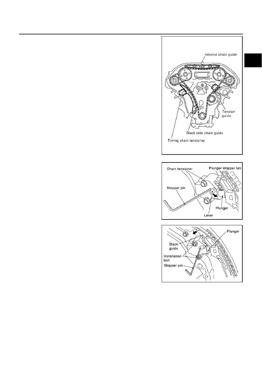
21. Remove internal chain guide, timing chain tensioner, tension

guide and slack guide.

Remove timing chain tensioner as follows:

a.

Pull lever down and release plunger stopper tab.

Plunger stopper tab can be pushed up to release (coaxial
structure with lever).

b.

Insert stopper pin into tensioner body hole to hold lever, and
keep the tab released.

NOTE:
 An Allen wrench [2.5 mm (0.098 in)] is used for a stopper pin as
an example.

c.

Insert plunger into tensioner body by pressing the slack guide.

d.

Keep the slack guide pressed and hold it by pushing the stopper
pin through the lever hole and body hole.

e.

Remove the mounting bolts and remove the timing chain ten-
sioner.

22. Remove timing chain (primary) and crankshaft sprocket.

CAUTION:

After removing timing chain, do not turn the crankshaft and camshaft separately, or the valves
will strike the piston heads.

SEM731G

SEM732G

SEM733G

EM-58

TIMING CHAIN

Revision; 2004 April

2003 Murano

23. Attach a suitable stopper pin to the RH and LH camshaft chain

tensioners (for secondary timing chains).

NOTE:
For removal and installation of secondary chain tensioner, refer
to 

EM-70, "CAMSHAFT"

 . (Removing No. 1 camshaft bracket is

required.)

24. Remove intake and exhaust camshaft sprocket bolts.

Apply paint to timing chain and camshaft sprockets for align-
ment during installation.

Secure the hexagonal portion of the camshaft using a wrench
to loosen the mounting bolts.

25. Remove secondary timing chain together with camshaft sprock-

ets.

Turn camshaft slightly to secure slackness of timing chain on
chain tensioner side.

Insert 0.5 mm (0.020 in) thick metal or resin plate between
timing chain and chain tensioner plunger (guide). Remove
secondary timing chain together with camshaft sprockets with
timing chain loose from guide groove.

CAUTION:

Be careful of plunger coming-off when removing timing
chain. This is because plunger of chain tensioner moves
during operation, leading to coming-off of fixed stopper
pin. 

NOTE:
Camshaft sprocket (INT) is two-for-one structure of primary and secondary sprockets.

When handling camshaft sprocket (INT), be careful of the fol-
lowing:

CAUTION:

Handle carefully to avoid any shock to camshaft
sprocket.

Do not disassemble. (Never loosen bolts “A” and “B”
as shown).

26. Remove chain tension guide.

SEM923G

KBIA1698J

SEM922G

SEM734G

TIMING CHAIN

EM-59

C

D

E

F

G

H

I

J

K

L

M

A

EM

Revision; 2004 April

2003 Murano

27. Remove rear timing chain case as follows:

a.

Loosen and remove mounting bolts in reverse order as shown.

b.

Cut the sealant using a seal cutter [special service tool:
KV10111100 (J37228)] or an equivalent tool and remove rear
timing chain case.

CAUTION:

Do not remove plate metal cover of oil passage.

After removing chain case, do not apply any load which
affects flatness.

28. Remove RH and LH camshaft chain tensioners from cylinder head as follows if necessary.

a.

Remove No.1 camshaft brackets. Refer to 

EM-71, "REMOVAL"

 .

b.

Remove secondary chain tensioners with stopper pin attached.

29. Use a scraper to remove all traces of liquid gasket from front

and rear timing chain cases, and opposite mating surfaces.

Remove old liquid gasket from the bolt hole and thread.

SEM735G

KBIA1307E

SEM737G

SEM161F

EM-60

TIMING CHAIN

Revision; 2004 April

2003 Murano

30. Use a scraper to remove all traces of liquid gasket from water

pump cover, chain tensioner cover and intake valve timing con-
trol covers.

INSPECTION AFTER REMOVAL

Check for cracks and any excessive wear at the roller links of the
timing chain. Replace the timing chain as necessary.

INSTALLATION

NOTE:
The below figure shows the relationship between the mating mark on each timing chain and that on the corre-
sponding sprocket, with the components installed.

1.

Install RH and LH camshaft chain tensioners to cylinder head as follows if removed. Refer to 

EM-74,

"INSTALLATION"

 .

SEM926E

PBIC0282E

KBIA1053E

TIMING CHAIN

EM-61

C

D

E

F

G

H

I

J

K

L

M

A

EM

Revision; 2004 April

2003 Murano

a.

Install secondary chain tensioners with stopper pin attached and
new O-ring.

b.

Install No.1 camshaft brackets. Refer to 

EM-74, "INSTALLA-

TION"

 .

2.

Install O-rings onto cylinder block.

3.

Install O-rings to cylinder head.

4.

Apply liquid gasket to rear timing chain case back side as shown.

Use Genuine RTV Silicone Sealant or equivalent. Refer to 

GI-46, "RECOMMENDED CHEMICAL

PRODUCTS AND SEALANTS"

 .

PBIC0788E

SEM945G

PBIC1131E

EM-62

TIMING CHAIN

Revision; 2004 April

2003 Murano

5.

Align the rear timing chain case and water pump assembly with the dowel pins (RH and LH) on the cylin-
der block and install the case.

Make sure the O-rings stay in place during installation to cylinder block and cylinder head.

a.

Tighten the mounting bolts in the numerical order as shown.

There are two bolt lengths used. Follow the below for proper
bolt length specifications.

b.

After all bolts are temporarily tightened, retighten them to the
specification in the numerical order as shown.

If the RTV Silicone Sealant protrudes, wipe it off immediately.

6.

After installing rear timing chain case, check surface height difference between following parts on oil pan
mounting surface.

If not within standard, repeat above installation procedure.

7.

Install chain tension guide.

8.

Position the crankshaft so No. 1 piston is set at TDC on the
compression stroke.

Make sure that the dowel pin hole, dowel pin and crankshaft
key are located as shown.

CAUTION:

Hole on small dia. side must be used for intake side dowel pin hole. Do not misidentify (ignore big
dia. side).

9.

Install the timing chains (secondary) and camshaft sprockets.

CAUTION:

Matching marks between the timing chain and sprockets
slip easily. Confirm all matching mark positions repeatedly
during the installation process.

a.

Push the plunger of the secondary chain tensioner and keep it
pressed in with a stopper pin.

Bolt length:

Bolt position

20 mm (0.79 in)

: 1, 2, 3, 6, 7, 8, 9, 10

16 mm (0.63 in)

: Except the above

 : 11.7 - 13.7 N·m (1.2 - 1.4 kg-m, 9 - 10 ft-lb)

Standard

Rear timing chain case to cylinder block:

–0.24 to 0.14 mm (–0.0094 to 0.0055 in)

Camshaft dowel pin hole (intake side)

: At cylinder head upper face side in each bank.

Camshaft dowel pin (exhaust side)

: At cylinder head upper face side in each bank.

Crankshaft key

: At cylinder head side of RH bank.

SEM735G

KBIA1073E

SEM430G

TIMING CHAIN

EM-63

C

D

E

F

G

H

I

J

K

L

M

A

EM

Revision; 2004 April

2003 Murano

b.

Install secondary timing chains and camshaft sprockets.

Align the mating marks on the secondary timing chain (gold
link) with the ones on the intake and exhaust sprockets
(stamped), and install them.
NOTE:

Mating marks for the intake sprocket are on the back side
of the secondary camshaft sprocket.

There are two types of mating marks, circle and oval types.
They should be used for the RH and LH banks, respec-
tively.

Align the dowel pin and pin hole on the camshaft with the
groove and dowel pin on the sprocket, and install them.

On the intake side, align the pin hole on the small diameter
side of the camshaft front end with the dowel pin on the back
side of the camshaft sprocket, and install them.

On the exhaust side, align the dowel pin on the camshaft front
end with the pin groove on the camshaft sprocket, and install
them.

Mounting bolts for the camshaft sprockets must be tightened
in the next step. Tightening them by hand is enough to prevent the dislocation of the dowel pins.

It may be difficult to visually check the dislocation of mating
marks during and after installation. To make the matching
easier, make a mating mark on the top of sprocket teeth and
its extended line in advance with paint.

10. After confirming the mating marks are aligned, tighten the cam-

shaft sprocket mounting bolts.

Secure the camshaft using a wrench at the hexagonal portion
to tighten the mounting bolts.

11. Pull the stopper pins out from the secondary timing chain ten-

sioners.

RH bank

: use circle type.

LH bank

: use oval type.

PBIC1117E

PBIC0891E

KBIA1698J

SEM923G

EM-64

TIMING CHAIN

Revision; 2004 April

2003 Murano

12. Install the primary timing chain as follows:

a.

Install the crankshaft sprocket.

Make sure the mating marks on the crankshaft sprocket face
the front of the engine.

b.

Install the primary timing chain.

Install primary timing chain so the mating mark (punched) on
camshaft sprocket is aligned with the yellow link on the timing
chain, while the mating mark (notched) on the crankshaft
sprocket is aligned with the orange one on the timing chain,
as shown.

When it is difficult to align mating marks of the primary timing
chain with each sprocket, gradually turn the camshaft using a
wrench on the hexagonal portion to align it with the mating
marks.

During alignment, be careful to prevent dislocation of mating
mark alignments of the secondary timing chains.

SEM929E

PBIC1132E

TIMING CHAIN

EM-65

C

D

E

F

G

H

I

J

K

L

M

A

EM

Revision; 2004 April

2003 Murano

13. Install the internal chain guide and tension guide.

14. Install slack guide.

Do not overtighten the slack guide mounting bolts. It is normal
for a gap to exist under the bolt seats when the mounting bolts
are tightened to specification.

15. Install chain tensioner for slack guide.

When installing the chain tensioner, push in the sleeve and
keep it pressed in with the stopper pin.

Remove any dirt and foreign materials completely from the
back and the mounting surfaces of the chain tensioner.

After installation, pull out the stopper pin by pressing the slack
guide.

16. Reconfirm that the mating marks on the sprockets and the timing chain have not slipped out of alignment.

SEM740G

SEM741G

SEM733G

EM-66

TIMING CHAIN

Revision; 2004 April

2003 Murano

17. Install new O-rings on the rear timing chain case.

18. Install the front oil seal on the front timing chain case. Apply

new engine oil to the oil seal edges.

Install it so that each seal lip is oriented as shown in figure. 

Using a suitable drift, press-fit oil seal until it becomes flush
with timing chain case end face.

Make sure the garter spring is in position and seal lip is not
inverted.

19. Install the water pump cover and the chain tensioner cover to

front cover.

Apply RTV Silicone Sealant or equivalent. Refer to 

GI-46,

"RECOMMENDED CHEMICAL PRODUCTS AND SEAL-
ANTS"

 .

SEM946G

SEM715A

PBIC0790E

SEM744GA

TIMING CHAIN

EM-67

C

D

E

F

G

H

I

J

K

L

M

A

EM

Revision; 2004 April

2003 Murano

20. Install front timing chain case as follows:

a.

Apply liquid gasket to front timing chain case back side as
shown.

b.

Install dowel pin on the rear timing chain case into dowel pin
hole on front timing chain case.

c.

Tighten bolts to the specified torque in order shown in the figure.

d.

After tightening, retighten them to specified torque in numerical
order shown in figure.

21. After installing the front timing chain case, check the surface

height difference between the following parts on the oil pan
mounting surface.

If not within specification, repeat the installation procedure.

22. Install RH and LH intake valve timing control covers as follows:

a.

Install seal rings in shaft grooves.

b.

Apply liquid gasket to the intake valve timing control covers.

Use Genuine RTV Silicone Sealant or equivalent. Refer to 

GI-

46, "RECOMMENDED CHEMICAL PRODUCTS AND SEAL-
ANTS"

 .

PBIC1133E

8 mm (0.31 in) dia. bolts

: 1, 2

 : 25.5 - 31.3 N·m (2.6 - 3.2 kg-m, 19 - 23 ft-lb)

6 mm (0.24 in) dia. bolts

: Except the above

 : 11.7 - 13.7 N·m (1.2 - 1.4 kg-m, 9 - 10 ft-lb)

SEM730G

Standard

Front timing chain case to rear timing chain case:

–0.14 to 0.14 mm (–0.005 to 0.0055 in)

SEM943G

SEM747G

EM-68

TIMING CHAIN

Revision; 2004 April

2003 Murano

c.

Install collared O-ring in front cover oil hole (LH and RH sides).

d.

Being careful not to move the seal ring from the installation
groove, align the dowel pins on the chain case with the holes to
install the intake valve timing control covers.

e.

Tighten bolts in the numerical order as shown.

23. Install RH and LH rocker covers. Refer to 

EM-43, "ROCKER COVER"

 .

24. Install crankshaft pulley as follows:
a.

Fix crankshaft using a hammer shaft or an equivalent tool.

b.

Install crankshaft pulley, taking care not to damage front oil seal.

When press-fitting crankshaft pulley with a plastic hammer, tap on its center portion (not circumfer-
ence).

c.

Tighten bolt to 39.2 to 49.0 N·m (4.0 to 5.0 kg-m, 29 to 36 ft-lb).

d.

Put a paint mark on crankshaft pulley aligning with angle mark
on crankshaft pulley bolt. Then, further retighten bolt by 60 to 65
degrees [Target: 60 degrees (equivalent to one graduation)].

25. Rotate crankshaft pulley in normal direction (clockwise when viewed from front) to confirm it turns

smoothly.

26. For the following operations, perform steps in the reverse order of removal.

NOTE:
If hydraulic pressure inside chain tensioner drops after removal/installation, slack in the guide may gener-
ate a pounding noise during and just after engine start. However, this does not indicate an unusualness.
Noise will stop after hydraulic pressure rises.

SEM948G

PBIC0918E

SEM751G

TIMING CHAIN

EM-69

C

D

E

F

G

H

I

J

K

L

M

A

EM

Revision; 2004 April

2003 Murano

INSPECTION AFTER INSTALLATION

Before starting engine, check the levels of engine coolant, lubrications and working oils. If less than
required quantity, fill to the specified level.

Use procedure below to check for fuel leakage.

Turn ignition switch ON (with engine stopped). With fuel pressure applied to fuel piping, check for fuel
leakage at connection points.

Start engine. With engine speed increased, check again for fuel leakage at connection points.

Run engine to check for unusual noise and vibration.

Warm up engine thoroughly to make sure there is no leakage of engine coolant, lubricants, working oil,
fuel and exhaust gas.

Bleed air from passages in pipes and tubes of applicable lines, such as in cooling system.

After cooling down engine, again check amounts of engine coolant, lubricants, oil, and fluid. Refill to spec-
ified level, if necessary.

EM-70

CAMSHAFT

Revision; 2004 April

2003 Murano

CAMSHAFT

PFP:13001

Removal and Installation

ABS0032R

1.

Intake valve timing control solenoid 
valve

2.

Gasket

3.

Camshaft bracket (No.2 to No.4)

4.

Camshaft (EXH)

5.

Camshaft (INT)

6.

Camshaft bracket (No.1)

7.

Dowel pin

8.

Valve lifter

9.

O-ring

10. Chain tensioner (Secondary)

11.

Spring

12. Plunger

13. Cylinder head (RH bank)

14.

Cylinder head (LH bank)

15.

Camshaft position sensor (PHASE) 
(RH bank)

16.

Camshaft position sensor (PHASE) 
(LH bank)

PBIC1769E

CAMSHAFT

EM-71

C

D

E

F

G

H

I

J

K

L

M

A

EM

Revision; 2004 April

2003 Murano

REMOVAL

1.

Remove front timing chain case, camshaft sprocket, timing chain and rear timing chain case. Refer to 

EM-

54, "TIMING CHAIN"

 .

2.

If necessary, remove camshaft position sensor (PHASE) (RH
and LH banks) from cylinder head back side.

CAUTION:

Handle carefully to avoid dropping and shocks.

Do not disassemble.

Do not allow metal powder to adhere to magnetic part at
sensor tip.

Do not place sensors in a location where they are
exposed to magnetism.

3.

Remove the intake valve timing control solenoid valves.

Discard the intake valve timing control solenoid valve gaskets
and use new gaskets for installation.

4.

Remove the intake and exhaust camshaft brackets.

Mark the camshafts, camshaft brackets, and bolts so they are
placed in the same position and direction for installation.

Equally loosen the camshaft bracket bolts in several steps in
the numerical order shown.

5.

Remove camshaft.

6.

Remove valve lifter.

Identify installation positions, and store them without mixing them up.

KBIA1046E

SEM443GA

SEM856E

SEM857E

EM-72

CAMSHAFT

Revision; 2004 April

2003 Murano

7.

Remove secondary timing chain tensioner from cylinder head.

Remove secondary chain tensioner with its stopper pin
attached.

NOTE:
Stopper pin was attached when secondary timing chain was
removed.

INSPECTION AFTER REMOVAL
Camshaft Runout

1.

Put V block on precise flat bed, and support No. 2 and No. 4
journal of camshaft.

2.

Set dial gauge vertically to No. 3 journal.

3.

Turn camshaft to one direction with hands, and measure cam-
shaft runout on dial gauge. (Total indicator reading)

4.

If it exceeds the limit, replace camshaft.

Camshaft Cam Height

1.

Measure camshaft cam height.

2.

If wear is beyond the limit, replace camshaft.

Camshaft Journal Clearance

Outer Diameter of Camshaft Journal

Measure outer diameter of camshaft journal.

SEM947G

Limit

: 0.05 mm (0.0020 in)

PBIC0929E

Standard cam height (intake and exhaust)

: 44.865 - 45.055 mm (1.7663 - 1.7738 in)

Cam wear limit

: 0.2 mm (0.008 in)

EMQ0072D

Standard outer diameter:

   No. 1 : 25.935 - 25.955 mm (1.0211 - 1.0218 in)

   No. 2, 3, 4 : 23.445 - 23.465 mm (0.9230 - 0.9238 in)

PBIC0040E


Content      ..     126      127      128      129     ..