Nissan Murano Z50 (2003 year). Manual - part 125


  Index      Manuals     Nissan Murano Z50 (2003 year) - Service and Repair Manual


Search            copyright infringement  


Content      ..     123      124      125      126     ..


Nissan Murano Z50 (2003 year). Manual - part 125


NOISE, VIBRATION AND HARSHNESS (NVH) TROUBLESHOOTING

EM-9

C

D

E

F

G

H

I

J

K

L

M

A

EM

Revision; 2004 April

2003 Murano

NOISE, VIBRATION AND HARSHNESS (NVH) TROUBLESHOOTING

PFP:00003

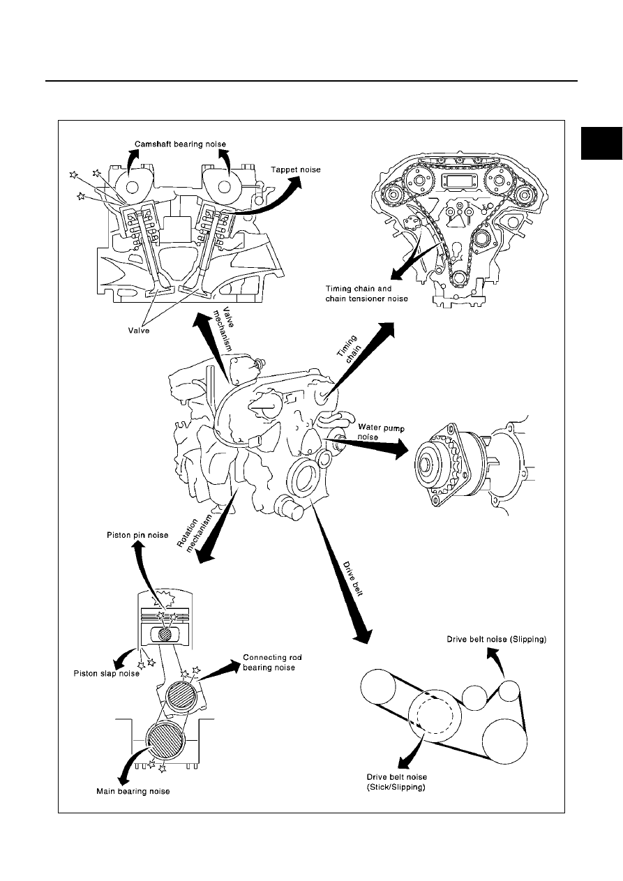
NVH Troubleshooting —Engine Noise

ABS00327

SEM706G

EM-10

NOISE, VIBRATION AND HARSHNESS (NVH) TROUBLESHOOTING

Revision; 2004 April

2003 Murano

Use the Chart Below to Help You Find the Cause of the Symptom.

ABS00328

1.

Locate the area where noise occurs.

2.

Confirm the type of noise.

3.

Specify the operating condition of engine.

4.

Check specified noise source.

If necessary, repair or replace these parts.

A: Closely related

B: Related

C: Sometimes related

—: Not related

Location 

of noise

Type of 

noise

Operating condition of engine

Source of 

noise

Check item

Refer-

ence page

Before 

warm-

up

After 

warm-

up

When 

start-

ing

When 

idling

When 

racing

While 

driving

Top of 
engine
Rocker 
cover
Cylinder 
head

Ticking or 
clicking

C

A

A

B

Tappet 
noise

Valve clearance

EM-77

Rattle

C

A

A

B

C

Camshaft 
bearing 
noise

Camshaft runout
Camshaft journal clear-
ance

EM-72
EM-72

Crank-
shaft pul-
ley
Cylinder 
block 
(Side of 
engine)
Oil pan

Slap or 
knock

A

B

B

Piston pin 
noise

Piston and piston pin 
clearance
Connecting rod bush-
ing clearance

EM-115
EM-117

Slap or 
rap

A

B

B

A

Piston 
slap noise

Piston-to-bore clear-
ance
Piston ring side clear-
ance
Piston ring end gap
Connecting rod bend 
and torsion

EM-119
EM-116
EM-116
EM-116

Knock

A

B

C

B

B

B

Connect-
ing rod 
bearing 
noise

Connecting rod bush-
ing clearance (Small 
end)
Connecting rod bear-
ing clearance (Big end)

EM-117
EM-121

Knock

A

B

A

B

C

Main 
bearing 
noise

Main bearing oil clear-
ance
Crankshaft runout

EM-122
EM-121

Front of 
engine
Timing 
chain 
cover

Tapping or 
ticking

A

A

B

B

B

Timing 
chain and 
chain ten-
sioner 
noise

Timing chain cracks 
and wear
Timing chain tensioner 
operation

EM-60
EM-54

Front of 
engine

Squeak-
ing or fizz-
ing

A

B

B

C

Drive belts 
(Sticking 
or slip-
ping)

Drive belts deflection

EM-11

Creaking

A

B

A

B

A

B

Drive belts 
(Slipping)

Idler pulley bearing 
operation

Squall
Creak

A

B

B

A

B

Water 
pump 
noise

Water pump operation

CO-20, 
"WATER 
PUMP"

DRIVE BELTS

EM-11

C

D

E

F

G

H

I

J

K

L

M

A

EM

Revision; 2004 April

2003 Murano

DRIVE BELTS

PFP:02117

Checking Drive Belts

ABS00329

WARNING:

Be sure to perform when the engine is stopped.
1.

Inspect belts for cracks, fraying, wear and oil. If necessary, replace.

2.

Inspect drive belt deflection or tension at a point on the belt mid-
way between pulleys.

Inspection should be done only when engine is cold, or over
30 minutes after engine is stopped.

Measure belt tension with tension gauge (BT3373-F or equiv-
alent) at points marked   shown in the figure.

When measuring deflection, apply 98 N (10 kg, 22 lb) at the 
marked point.

Adjust if belt deflection exceeds the limit or if belt tension is
not within specifications.

CAUTION:

When checking belt deflection or tension immediately after installation, first adjust it to the
specified value. Then, after turning the crankshaft two turns or more, re-adjust to the specified
value to avoid variation in deflection between pulleys.

Tighten idler pulley lock nut by hand and measure deflec-
tion or tension without looseness.

Belt Deflection and Tension

*: If belt tension gauge cannot be installed at check points shown, check drive belt tension at different location on the belt.

Tension Adjustment

ABS0036V

CAUTION:

When belt is replaced with a new one, adjust it to value for “New belt” to accommodate for insuffi-
cient adaptability with pulley grooves.

PBIC1161E

PBIC1162E

Deflection adjustment                                Unit: mm (in)

Tension adjustment*                                 Unit: N (kg, lb)

Used belt

New belt

Used belt

New belt

Limit

After adjustment

Limit

 After adjustment

Alternator and 
air conditioner 
compressor

       7 (0.28)

       4.2 - 4.6
    (0.17 - 0.18)

      3.7 - 4.1
   (0.15 - 0.16)

294 (30, 66)

730 - 818

(74.5 - 83.5,

164 - 184)

838 - 926

(85.5 - 94.5,

188 - 208)

Power steering 
oil pump

      11 (0.43)

        7.3 - 8
    (0.29 - 0.30)

      6.5 - 7.2
   (0.26 - 0.28)

196 (20, 44)

495 - 583

(50.5 - 59.5,

111 - 131)

603 - 691

(61.5 - 70.5, 

135.6 - 155.4)

Applied pushing 
force

                             98 N (10 Kg, 22 lb)

                                            —

Portion

Belt tightening method for adjustment

Power steering oil pump belt

Adjusting bolt on power steering oil pump

Alternator and air conditioner compressor belt

Adjusting bolt on idler pulley

EM-12

DRIVE BELTS

Revision; 2004 April

2003 Murano

When deflection or tension of belt being used exceeds “Used belt limit”, adjust it to value for
“After adjustment of used belt”.

When checking belt deflection or tension immediately after installation, first adjust it to the speci-
fied value. Then, after turning the crankshaft two turns or more, re-adjust to the specified value to
avoid variation in deflection between pulleys.

When installing belt, make sure that it is correctly engaged with pulley groove.

Keep oil and water away from belt.

Do not twist or bend belt excessively.

ALTERNATOR AND AIR CONDITIONER COMPRESSOR BELT

1.

Remove splash guard (RH).

2.

Loosen idler pulley lock nut (A) and adjust tension by turning
adjusting bolt (B).

For specified belt tension, refer to 

EM-11, "Checking Drive

Belts"

 .

3.

Tighten lock nut (A).

4.

Tighten adjusting bolt (B).

POWER STEERING OIL PUMP BELT

1.

Remove splash guard (RH).

2.

Loosen adjusting bolt (C).

3.

Loosen power steering oil pump mounting bolt (D).

Bolt head (D) is engine rear side.

4.

Adjust by turning adjusting bolt (E).

For specified belt tension, refer to 

EM-11, "Checking Drive Belts"

 .

NOTE:
Adjusting bolt (E) is loosened with counter-clockwise rotation.

5.

Tighten bolt (C), then bolt (D).

Removal and Installation

ABS0036W

REMOVAL

1.

Remove splash guard (RH).

2.

Fully loosen each belt by following the guidelines in 

EM-11, "Tension Adjustment"

 . Remove alternator and

air conditioner compressor belt and then power steering oil pump belt.

CAUTION:

Grease is applied to idler pulley adjusting bolt. Be careful to keep grease away from the belt.


 : 30.4 - 39.2 N·m (3.1 - 3.9 kg-m, 23 - 28 ft-lb)


 : 3.9 - 6.9 N·m (0.4 - 0.7 kg-m, 35 - 61 in-lb)

PBIC1163E

Tightening torque:

Bolt (C) : 24.5 - 31.4 N·m (2.5 - 3.2 kg-m, 18 - 23 ft-lb)

Bolt (D) : 36.3 - 50.0 N·m (3.7 - 5.1 kg-m, 27 - 36 ft-lb)

DRIVE BELTS

EM-13

C

D

E

F

G

H

I

J

K

L

M

A

EM

Revision; 2004 April

2003 Murano

INSTALLATION

1.

Install belts to pulley in reverse order of removal.

CAUTION:

Make sure belt is correctly engaged with the pulley groove.

Check for oil and engine coolant on belt and each pulley groove.

2.

Adjust belt tension. Refer to 

EM-11, "Tension Adjustment"

 .

3.

Tighten each adjusting bolt and nut to the specified torque.

4.

Make sure that tension of each belt is within the standard.

EM-14

AIR CLEANER AND AIR DUCT

Revision; 2004 April

2003 Murano

AIR CLEANER AND AIR DUCT

PFP:16500

Removal and Installation

ABS0033C

REMOVAL

1.

Remove RH and LH both side radiator cover grills.

2.

Remove air duct (inlet).

3.

Disconnect harness connector from the mass air flow sensor.

4.

Disconnect the tube clamp at the electric throttle control actuator and at the mass air flow sensor.

5.

Remove PCV hose, air cleaner case (upper) with the mass air flow sensor attached.

6.

Remove mass air flow sensor from air cleaner case (upper), as necessary.

CAUTION:

Handle mass air flow sensor with care.

Do not shock it.

Do not disassemble it.

Do not touch its sensor.

7.

Remove resonator in the fender, lifting left fender protector, as necessary.

1.

Air cleaner case (lower)

2.

Air cleaner filter

3.

Air cleaner case (upper)

4.

Air duct assembly

5.

Harness bracket

6.

Mass air flow sensor

7.

O-ring

8.

PCV hose

9.

Clip

10. Radiator cover grill (RH side)

11. Air duct (inlet)

12.

Radiator cover grill (LH side)

13. Resonator

14. Bracket

15.

Grommet

16. Bracket

PBIC1806E

AIR CLEANER AND AIR DUCT

EM-15

C

D

E

F

G

H

I

J

K

L

M

A

EM

Revision; 2004 April

2003 Murano

INSTALLATION

Installation is in the reverse order of removal.

CHANGING AIR CLEANER FILTER

1.

Unhook the air cleaner case (lower) side clips and lift up the air cleaner case (upper).

2.

Remove the air cleaner filter.

PBIC1165E

EM-16

INTAKE MANIFOLD COLLECTOR

Revision; 2004 April

2003 Murano

INTAKE MANIFOLD COLLECTOR

PFP:14003

Removal and Installation

ABS0032E

1.

Electric throttle control actuator

2.

Gasket

3.

Intake manifold collector (upper)

4.

PCV hose

5.

Harness bracket

6.

Gasket

7.

Power valve

8.

VIAS control solenoid valve

9.

Vacuum tank

10. Gasket

11. Intake manifold collector (lower)

12.

EVAP canister purge volume control 
solenoid valve

13. Gasket

14. EVAP hose

15. Support bracket

PBIC1166E

INTAKE MANIFOLD COLLECTOR

EM-17

C

D

E

F

G

H

I

J

K

L

M

A

EM

Revision; 2004 April

2003 Murano

REMOVAL

WARNING:

To avoid the danger of being scalded, never drain the coolant when the engine is hot.
1.

Remove engine cover.

2.

Drain engine coolant, or when water hose is disconnected,
attach plug to prevent engine coolant leakage. Refer to 

CO-8,

"Changing Engine Coolant"

 .

CAUTION:

Perform when engine is cold.

3.

Remove air duct. Refer to 

EM-14, "AIR CLEANER AND AIR

DUCT"

 .

4.

Remove electric throttle control actuator.

Loosen bolts in the reverse order of that shown in the figure.

CAUTION:

Handle carefully to avoid any shock to the electric throt-
tle control actuator.

Do not disassemble.

5.

Disconnect vacuum hose and water hose from intake manifold collector (upper and lower).

6.

Disconnect EVAP canister purge volume control solenoid valve mounting bolt from intake manifold collec-
tor (lower).

7.

Remove VIAS control solenoid valve and vacuum tank.

8.

Remove the RH windshield wiper arm and RH front cowl top cover. Refer to 

EI-21, "COWL TOP"

 .

9.

Disconnect the power steering hose bracket.

10. Remove intake manifold collector support bracket.

11. Remove PCV hose [between intake manifold collector (upper) and RH rocker cover].

12. Loosen bolts in reverse order of illustration with power tool, and

remove intake manifold collector (upper and lower) assembly
with power tool.

PBIC1167E

SEM711G

SEM713G

EM-18

INTAKE MANIFOLD COLLECTOR

Revision; 2004 April

2003 Murano

13. Loosen bolts in reverse order of illustration to remove intake

manifold collector (upper) with power tool.

14. Remove power valve in reverse order of illustration.

INSPECTION AFTER REMOVAL
Surface Distortion

Using straightedge and feeler gauge, inspect the surface distor-
tion of intake manifold collector (lower).

If it exceeds the limit, replace the intake manifold collector.

INSTALLATION

Install in the reverse order of removal paying attention to the following.

Installation of Power Valve

Tighten in numerical order as shown in the figure.

SEM712G

SEM714G

Limit

: 0.1 mm (0.004 in)

PBIC1168E

 : 17.6 - 21.6 N·m (1.8 - 2.2 kg-m, 13 - 15 ft-lb)

SEM714G

INTAKE MANIFOLD COLLECTOR

EM-19

C

D

E

F

G

H

I

J

K

L

M

A

EM

Revision; 2004 April

2003 Murano

Installation of Intake Manifold Collector (Upper)

Tighten in numerical order as shown in the figure.

Installation of Intake Manifold Collector (Lower)

Tighten in numerical order as shown in the figure.

NOTE:
Tighten mounting bolts to secure gasket (lower), intake manifold col-
lector (lower), gasket (upper).

Installation of Electric Throttle Control Actuator 

Install gasket with three protrusions for installation check facing any direction other than upward or down-
ward.

Tighten in numerical order as shown in the figure.

Perform the “Throttle Valve Closed Position Learning” when har-
ness connector of the electric throttle control actuator is discon-
nected. Refer to 

EC-64, "Throttle Valve Closed Position

Learning"

 .

Perform the “Idle Air Volume Learning” and “Throttle Valve
Closed Position Learning” when the electric throttle control actu-
ator is replaced. Refer to 

EC-64, "Idle Air Volume Learning"

 .

 : 17.6 - 21.6 N·m (1.8 - 2.2 kg-m, 13 - 15 ft-lb)

SEM712G

 : 17.6 - 21.6 N·m (1.8 - 2.2 kg-m, 13 - 15 ft-lb)

SEM713G

 : 7.2 - 9.6 N·m (0.74 - 0.97 kg-m, 64 - 84 in-lb)

SEM711G

EM-20

INTAKE MANIFOLD

Revision; 2004 April

2003 Murano

INTAKE MANIFOLD

PFP:14003

Removal and Installation

ABS0033D

REMOVAL

1.

Release fuel pressure. Refer to 

EC-66, "FUEL PRESSURE RELEASE"

 .

2.

Remove intake manifold collector (upper and lower). Refer to 

EM-16, "INTAKE MANIFOLD COLLECTOR"

.

3.

Remove fuel tube and fuel injector assembly. Refer to 

EM-38, "FUEL INJECTOR AND FUEL TUBE"

4.

Loosen bolts and nuts in reverse order of illustration to remove
intake manifold assembly with power tool.

INSPECTION AFTER REMOVAL
Surface Distortion

Using straightedge and feeler gauge, inspect the surface distor-
tion of each surface on intake manifold.

If it exceeds the limit, replace the intake manifold.

1.

Intake manifold

2.

Gasket

PBIC1169E

PBIC0778E

Limit

: 0.1 mm (0.04 in)

PBIC0870E

INTAKE MANIFOLD

EM-21

C

D

E

F

G

H

I

J

K

L

M

A

EM

Revision; 2004 April

2003 Murano

INSTALLATION

Install in the reverse order of removal paying attention to the following.

Installation of Intake Manifold

If stud bolts were removed, install them and tighten to the torque
specified below.

Tighten all mounting bolts and nuts to specified torque in two or
more steps in numerical order shown in figure.

 : 9.8 - 11.8 N·m (1.0 - 1.2 kg-m, 87 - 104 in-lb)

 1st step

: 4.9 - 9.8 N·m (0.5 - 1.0 kg-m, 4 - 7 ft-lb)

 2nd step and after

: 26.5 - 31.4 N·m (2.7 - 3.2 kg-m, 20 - 23 ft-lb)

PBIC0778E

EM-22

EXHAUST MANIFOLD AND THREE WAY CATALYST

Revision; 2004 April

2003 Murano

EXHAUST MANIFOLD AND THREE WAY CATALYST

PFP:14004

Removal and Installation

ABS0032G

REMOVAL

WARNING:

Perform the work when the exhaust and cooling system have completely cooled down.

When removing the engine mounting through bolts and nuts, lift the engine up slightly for safety
with a transmission jack.  Refer to 

EM-95, "ENGINE ASSEMBLY"

 .

1.

Remove the exhaust front tube. Refer to 

EX-3, "Removal and Installation"

 .

2.

Remove rear engine mount insulator (2WD models) (when RH exhaust manifold and three way catalyst is
removed). Refer to 

EM-95, "ENGINE ASSEMBLY"

 .

3.

Remove the RH windshield wiper arm and RH front cowl top cover (when RH exhaust manifold and three
way catalyst is removed). Refer to 

EI-21, "COWL TOP"

 .

1.

Heated oxygen sensor 1 (bank 1)

2.

Exhaust manifold cover

3.

Exhaust manifold (RH bank)

4.

Gasket

5.

Gasket

6.

Three way catalyst (manifold) (RH 
bank)

7.

Heated oxygen sensor 2 (bank 1)

8.

Support (RH)

9.

Three way catalyst heat shield

10.

Three way catalyst (manifold) (LH 
bank)

11. Heated oxygen sensor 2 (bank 2)

12. Support (LH)

13. Exhaust manifold cover

14. Exhaust manifold (LH bank)

15. Heated oxygen sensor 1 (bank 2)

PBIC1170E

EXHAUST MANIFOLD AND THREE WAY CATALYST

EM-23

C

D

E

F

G

H

I

J

K

L

M

A

EM

Revision; 2004 April

2003 Murano

4.

Remove heated oxygen sensor 1 and 2 on both LH and RH
bank.

a.

Remove harness connector of each heated oxygen sensor, and
disconnect the harness from the bracket and middle clamp.

b.

Remove both heated oxygen sensors with heated oxygen sen-
sor wrench [special service tool: KV10117100 (J3647-A) or
KV10117200 (J38365)].

CAUTION:

Be careful not to damage heated oxygen sensor.

Discard any heated oxygen sensor which has been
dropped from a height of more than 0.5 m (19.7 in) onto a
hard surface such as a concrete floor; replace with a new sensor.

5.

Remove the exhaust manifold covers and the three way catalyst heat shields.

6.

Remove bolts in the reverse order of illustration to remove three
way catalyst supports (RH and LH).

7.

Remove the three way catalyst (manifold) (RH bank) and three way catalyst (manifold) (LH bank) by loos-
ening the bolts first and then removing the nuts.

8.

Remove the exhaust manifolds.

Loosen the nuts in the reverse order as shown.

PBIC1182E

PBIC1174E

PBIC1171E

PBIC1172E

EM-24

EXHAUST MANIFOLD AND THREE WAY CATALYST

Revision; 2004 April

2003 Murano

INSPECTION AFTER REMOVAL
Surface Distortion

Use a reliable straightedge and feeler gauge to check the flat-
ness of the exhaust manifold mating surfaces.

If it exceeds the limit, replace the exhaust manifold.

INSTALLATION

Installation is in the reverse order of removal paying attention to the following.

CAUTION:

When using the heated oxygen sensor wrench [special service tool: KV10117200 (J38365)], tighten
to the middle of specified torque range, because the length of the tool may increase the actual
tightness. Do not tighten to the maximum specified torque range.

Before installing a heated oxygen sensor, clean the threads on the exhaust manifold using the
oxygen sensor thread cleaner tool (commercial service tool), and apply anti-seize lubricant.

Do not over-torque the heated oxygen sensors. Doing so may cause damage to the heated oxygen
sensors.

Exhaust Manifold

Install the exhaust manifold nuts in the numerical order as
shown.

Limit

: 0.3 mm (0.012 in)

PBIC1173E

PBIC1171E

PBIC1172E


Content      ..     123      124      125      126     ..