Nissan Murano Z50 (2003 year). Manual - part 103


  Index      Manuals     Nissan Murano Z50 (2003 year) - Service and Repair Manual


Search            copyright infringement  


Content      ..     101      102      103      104     ..


Nissan Murano Z50 (2003 year). Manual - part 103


DTC P0447 EVAP CANISTER VENT CONTROL VALVE

EC-367

C

D

E

F

G

H

I

J

K

L

M

A

EC

Revision; 2004 April

2003 Murano

3. 

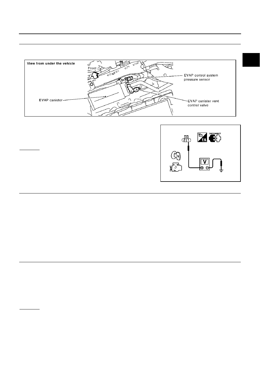
CHECK EVAP CANISTER VENT CONTROL VALVE POWER SUPPLY CIRCUIT

1.

Turn ignition switch “OFF”.

2.

Disconnect EVAP canister vent control valve harness connector.

3.

Turn ignition switch “ON”.

4.

Check voltage between EVAP canister vent control valve termi-
nal 1 and ground with CONSULT-II or tester.

OK or NG

OK

>> GO TO 5.

NG

>> GO TO 4.

4. 

DETECT MALFUNCTIONING PART

Check the following.

Harness connectors E110, M7

Harness connectors M10, B3

IPDM E/R harness connector E8

Harness for open or short between EVAP canister vent control valve and IPDM E/R

Harness for open or short between EVAP canister vent control valve and ECM

>> Repair harness or connectors.

5. 

CHECK EVAP CANISTER VENT CONTROL VALVE OUTPUT SIGNAL CIRCUIT FOR OPEN AND 

SHORT

1.

Turn ignition switch “OFF”.

2.

Disconnect ECM harness connector.

3.

Check harness continuity between ECM terminal 117 and EVAP canister vent control valve terminal 2.
Refer to Wiring Diagram.

4.

Also check harness for short to ground and short to power.

OK or NG

OK

>> GO TO 7.

NG

>> GO TO 6.

Voltage: Battery voltage

PBIB1365E

PBIB0152E

Continuity should exist.

EC-368

DTC P0447 EVAP CANISTER VENT CONTROL VALVE

Revision; 2004 April

2003 Murano

6. 

DETECT MALFUNCTIONING PART

Check the following.

Harness connectors B3, M10

Harness for open or short between EVAP canister vent control valve and ECM

>> Repair open circuit or short to ground or short to power in harness or connectors.

7. 

CHECK RUBBER TUBE FOR CLOGGING

1.

Disconnect rubber tube connected to EVAP canister vent control valve.

2.

Check the rubber tube for clogging.

OK or NG

OK

>> GO TO 8.

NG

>> Clean the rubber tube using an air blower.

8. 

CHECK EVAP CANISTER VENT CONTROL VALVE

Refer to 

EC-368, "Component Inspection"

 .

OK or NG

OK

>> GO TO 9.

NG

>> Replace EVAP canister vent control valve.

9. 

CHECK INTERMITTENT INCIDENT

Refer to 

EC-151, "TROUBLE DIAGNOSIS FOR INTERMITTENT INCIDENT"

 .

>> INSPECTION END

Component Inspection

ABS004H3

EVAP CANISTER VENT CONTROL VALVE

 With CONSULT-II

1.

Remove EVAP canister vent control valve from EVAP canister.

2.

Check portion B  of EVAP canister vent control valve for being
rusted.
If NG, replace EVAP canister vent control valve.
If OK, go to next step.

3.

Reconnect harness connectors disconnected.

4.

Turn ignition switch “ON”.

5.

Perform “VENT CONTROL/V” in “ACTIVE TEST” mode.

6.

Check air passage continuity and operation delay time.
Make sure new O-ring is installed properly.

Operation takes less than 1 second.

If NG, replace EVAP canister vent control valve.
If OK, go to next step.

7.

Clean the air passage (Portion A  to B ) of EVAP canister vent control valve using an air blower.

PBIB1033E

Condition VENT CONTROL/V

Air passage continuity between A and B

ON

No

OFF

Yes

PBIB0151E

DTC P0447 EVAP CANISTER VENT CONTROL VALVE

EC-369

C

D

E

F

G

H

I

J

K

L

M

A

EC

Revision; 2004 April

2003 Murano

8.

Perform step 6 again.

 Without CONSULT-II

1.

Remove EVAP canister vent control valve from EVAP canister.

2.

Check portion B  of EVAP canister vent control valve for being
rusted.

3.

Check air passage continuity and operation delay time under the
following conditions.
Make sure new O-ring is installed properly.

Operation takes less than 1 second.

If NG, replace EVAP canister vent control valve.
If OK, go to next step.

4.

Clean the air passage (Portion A  to B ) of EVAP canister vent control valve using an air blower.

5.

Perform step 3 again.

PBIB1033E

Condition

Air passage continuity between A and B

12V direct current supply between
 terminals 1 and 2

No

OFF

Yes

PBIB1034E

EC-370

DTC P0451 EVAP CONTROL SYSTEM PRESSURE SENSOR

Revision; 2004 April

2003 Murano

DTC P0451 EVAP CONTROL SYSTEM PRESSURE SENSOR

PFP:22365

Component Description

ABS005GL

The EVAP control system pressure sensor detects pressure in the purge line. The sensor output voltage to the
ECM increases as pressure increases.

CONSULT-II Reference Value in Data Monitor Mode

ABS005GM

Specification data are reference values.

On Board Diagnosis Logic

ABS005GN

NOTE:
If DTC P0451 is displayed with DTC P1229, first perform the trouble diagnosis for DTC P1229. Refer to

EC-512

 .

PBIB1365E

PBIB1207E

MONITOR ITEM

CONDITION

SPECIFICATION

EVAP SYS PRES

Ignition switch: ON

Approx. 1.8 - 4.8V

DTC No.

Trouble diagnosis name

DTC detecting condition

Possible cause

P0451
0451

EVAP control system 
pressure sensor perfor-
mance

ECM detects a sloshing signal from the EVAP 
control system pressure sensor

Harness or connectors

EVAP control system pressure sensor

DTC P0451 EVAP CONTROL SYSTEM PRESSURE SENSOR

EC-371

C

D

E

F

G

H

I

J

K

L

M

A

EC

Revision; 2004 April

2003 Murano

DTC Confirmation Procedure

ABS005GO

NOTE:
If “DTC Confirmation Procedure” has been previously conducted, always turn ignition switch “OFF” and wait at
least 10 seconds before conducting the next test.

 WITH CONSULT-II

1.

Turn ignition switch “OFF” and wait at least 10 seconds.

2.

Turn ignition switch “ON” and select “DATA MONITOR” mode
with CONSULT-II.

3.

Start engine and wait at least 40 seconds.

NOTE:
Do not depress accelerator pedal even slightly.
If 1st trip DTC is detected, go to 

EC-371, "Diagnostic Procedure"

.

 WITH GST

Follow the procedure “WITH CONSULT-II” above.

Diagnostic Procedure

ABS005GP

1. 

CHECK EVPA CONTROL SYSTEM PRESSURE SENSOR CONNECTOR FOR WATER

1.

Disconnect EVAP control system pressure sensor harness connector.

2.

Check sensor harness connector for water.

OK or NG

OK

>> GO TO 2.

NG

>> Repair or replace harness connector.

2. 

CHECK EVAP CONTROL SYSTEM PRESSURE SENSOR

Refer to 

EC-372, "Component Inspection"

 .

OK or NG

OK

>> GO TO 3.

NG

>> Replace EVAP control system pressure sensor.

3. 

CHECK INTERMITTENT INCIDENT

Refer to 

EC-151, "TROUBLE DIAGNOSIS FOR INTERMITTENT INCIDENT"

 .

For wiring diagram, refer to 

EC-375

 .

>> INSPECTION END

SEF194Y

Water should not exist.

PBIB1365E

EC-372

DTC P0451 EVAP CONTROL SYSTEM PRESSURE SENSOR

Revision; 2004 April

2003 Murano

Component Inspection

ABS005GQ

EVAP CONTROL SYSTEM PRESSURE SENSOR

1.

Remove EVAP control system pressure sensor with its harness connector connected.

2.

Remove EVAP control system pressure sensor from EVAP canister.
Do not reuse the O-ring, replace it with a new one.

3.

Install a vacuum pump to EVAP control system pressure sensor.

4.

Turn ignition switch “ON” and check output voltage between
ECM terminal 32 and ground under the following conditions.

CAUTION:

Always calibrate the vacuum pump gauge when using it.

Do not apply below -93.3 kPa (-700 mmHg, -27.56 inHg) or
pressure over 101.3 kPa (760 mmHg, 29.92 inHg).

5.

If NG, replace EVAP control system pressure sensor.

Applied vacuum kPa

(mmHg, inHg)

Voltage V

Not applied

1.8 - 4.8

-26.7 (-200, -7.87)

2.1 to 2.5V lower than above value

PBIB1173E

DTC P0452 EVAP CONTROL SYSTEM PRESSURE SENSOR

EC-373

C

D

E

F

G

H

I

J

K

L

M

A

EC

Revision; 2004 April

2003 Murano

DTC P0452 EVAP CONTROL SYSTEM PRESSURE SENSOR

PFP:25085

Component Description

ABS004H4

The EVAP control system pressure sensor detects pressure in the purge line. The sensor output voltage to the
ECM increases as pressure increases.

CONSULT-II Reference Value in Data Monitor Mode

ABS004H5

Specification data are reference values.

On Board Diagnosis Logic

ABS004H6

NOTE:
If DTC P0452 is displayed with DTC P1229, first perform the trouble diagnosis for DTC P1229. Refer to

EC-512

 .

PBIB1365E

PBIB1207E

MONITOR ITEM

CONDITION

SPECIFICATION

EVAP SYS PRES

Ignition switch: ON

Approx. 1.8 - 4.8V

DTC No.

Trouble diagnosis name

DTC detecting condition

Possible cause

P0452
0452

EVAP control system 
pressure sensor low 
input

An excessively low voltage from the sensor is 
sent to ECM.

Harness or connectors
(The sensor circuit is open or shorted.)

EVAP control system pressure sensor

EC-374

DTC P0452 EVAP CONTROL SYSTEM PRESSURE SENSOR

Revision; 2004 April

2003 Murano

DTC Confirmation Procedure

ABS004H7

NOTE:
If “DTC Confirmation Procedure” has been previously conducted, always turn ignition switch “OFF” and wait at
least 10 seconds before conducting the next test.
TESTING CONDITION:
Always perform test at a temperature of 5

°

C (41

°

F) or more.

 WITH CONSULT-II

1.

Start engine and warm it up to normal operating temperature.

2.

Turn ignition switch “OFF” and wait at least 10 seconds.

3.

Turn ignition switch “ON”.

4.

Select “DATA MONITOR” mode with CONSULT-II.

5.

Make sure that “FUEL T/TEMP SE” is more than 0

°

C (32

°

F).

6.

Start engine and wait at least 20 seconds.
If 1st trip DTC is detected, go to 

EC-376, "Diagnostic Procedure"

.

 WITH GST

1.

Start engine and warm it up to normal operating temperature.

2.

Check that voltage between ECM terminal 107 (Fuel tank tem-
perature sensor signal) and ground is less than 4.2V.

3.

Turn ignition switch “OFF” and wait at least 10 seconds.

4.

Start engine and wait at least 20 seconds.

5.

Select “MODE 7” with GST.
If 1st trip DTC is detected, go to 

EC-376, "Diagnostic Procedure"

.

SEF194Y

PBIB1110E

DTC P0452 EVAP CONTROL SYSTEM PRESSURE SENSOR

EC-375

C

D

E

F

G

H

I

J

K

L

M

A

EC

Revision; 2004 April

2003 Murano

Wiring Diagram

ABS004H8

TBWA0372E

EC-376

DTC P0452 EVAP CONTROL SYSTEM PRESSURE SENSOR

Revision; 2004 April

2003 Murano

Specification data are reference values and are measured between each terminal and ground.

CAUTION:

Do not use ECM ground terminals when measuring input/output voltage. Doing so may result in dam-
age to the ECM's transistor. Use a ground other than ECM terminals, such as the ground.

Diagnostic Procedure

ABS004H9

1. 

RETIGHTEN GROUND SCREWS

Loosen and retighten engine ground screws.

>> GO TO 2.

2. 

CHECK CONNECTOR

1.

Disconnect EVAP control system pressure sensor harness connector.

2.

Check sensor harness connector for water.

OK or NG

OK

>> GO TO 3.

NG

>> Repair or replace harness connector.

TER-

MINAL 

NO.

WIRE 

COLOR

ITEM

CONDITION

DATA (DC Voltage)

32

BR

EVAP control system pres-
sure sensor

[Ignition switch “ON”]

Approximately 1.8 - 4.8V

48

G/O

Sensors' power supply
(EVAP control system pres-
sure sensor)

[Ignition switch “ON”]

Approximately 5V

67

B

Sensors' ground
(MAF sensor / IAT sensor / 
PSP sensor / EVAP control 
system pressure sensor / 
ASCD steering switch / 
Refrigerant pressure sen-
sor)

[Engine is running]

Warm-up condition

Idle speed

Approximately 0V

PBIB1298E

Water should not exist.

PBIB1365E

DTC P0452 EVAP CONTROL SYSTEM PRESSURE SENSOR

EC-377

C

D

E

F

G

H

I

J

K

L

M

A

EC

Revision; 2004 April

2003 Murano

3. 

CHECK EVAP CONTROL SYSTEM PRESSURE SENSOR POWER SUPPLY CIRCUIT

1.

Turn ignition switch “ON”.

2.

Check voltage between EVAP control system pressure sensor
terminal 3 and ground with CONSULT-II or tester.

OK or NG

OK

>> GO TO 5.

NG

>> GO TO 4.

4. 

DETECT MALFUNCTIONING PART

Check the following.

Harness connectors B2, M9

Harness connectors M82, F102

Harness for open or short between EVAP control system pressure sensor and ECM

>> Repair open circuit or short to ground or short to power in harness or connectors.

5. 

CHECK EVAP CONTROL SYSTEM PRESSURE SENSOR GROUND CIRCUIT FOR OPEN AND 

SHORT

1.

Turn ignition switch “OFF”.

2.

Check harness continuity between EVAP control system pressure sensor terminal 1 and engine ground.
Refer to Wiring Diagram.

3.

Also check harness for short to ground and short to power.

OK or NG

OK

>> GO TO 7.

NG

>> GO TO 6.

6. 

DETECT MALFUNCTIONING PART

Check the following.

Harness connectors B2, M9

Harness connectors M82, F102

Joint connector-3

Harness for open or short between EVAP control system pressure sensor and ECM

>> Repair open circuit or short to ground or short to power in harness or connectors.

Voltage: Approximately 5V

PBIB0138E

Continuity should exist.

EC-378

DTC P0452 EVAP CONTROL SYSTEM PRESSURE SENSOR

Revision; 2004 April

2003 Murano

7. 

CHECK EVAP CONTROL SYSTEM PRESSURE SENSOR INPUT SIGNAL CIRCUIT FOR OPEN AND 

SHORT

1.

Disconnect ECM harness connector.

2.

Check harness continuity between ECM terminal 32 and EVAP control system pressure sensor terminal
2.
Refer to Wiring Diagram.

3.

Also check harness for short to ground and short to power.

OK or NG

OK

>> GO TO 9.

NG

>> GO TO 8.

8. 

DETECT MALFUNCTIONING PART

Check the following.

Harness connectors B2, M9

Harness connectors M82, F102

Harness for open or short between EVAP control system pressure sensor and ECM

>> Repair open circuit or short to ground or short to power in harness or connectors.

9. 

CHECK EVAP CONTROL SYSTEM PRESSURE SENSOR

Refer to 

EC-378, "Component Inspection"

 .

OK or NG

OK

>> GO TO 10.

NG

>> Replace EVAP control system pressure sensor.

10. 

CHECK INTERMITTENT INCIDENT

Refer to 

EC-151, "TROUBLE DIAGNOSIS FOR INTERMITTENT INCIDENT"

 .

>> INSPECTION END

Component Inspection

ABS004HA

EVAP CONTROL SYSTEM PRESSURE SENSOR

1.

Remove EVAP control system pressure sensor with its harness connector connected.

2.

Remove EVAP control system pressure sensor from EVAP canister.
Do not reuse the O-ring, replace it with a new one.

3.

Install a vacuum pump to EVAP control system pressure sensor.

4.

Turn ignition switch “ON” and check output voltage between
ECM terminal 32 and ground under the following conditions.

CAUTION:

Always calibrate the vacuum pump gauge when using it.

Do not apply below -93.3 kPa (-700 mmHg, -27.56 inHg) or
pressure over 101.3 kPa (760 mmHg, 29.92 inHg).

5.

If NG, replace EVAP control system pressure sensor.

Continuity should exist.

Applied vacuum kPa

(mmHg, inHg)

Voltage V

Not applied

1.8 - 4.8

-26.7 (-200, -7.87)

2.1 to 2.5V lower than above value

PBIB1173E

DTC P0453 EVAP CONTROL SYSTEM PRESSURE SENSOR

EC-379

C

D

E

F

G

H

I

J

K

L

M

A

EC

Revision; 2004 April

2003 Murano

DTC P0453 EVAP CONTROL SYSTEM PRESSURE SENSOR

PFP:25085

Component Description

ABS004HB

The EVAP control system pressure sensor detects pressure in the purge line. The sensor output voltage to the
ECM increases as pressure increases.

CONSULT-II Reference Value in Data Monitor Mode

ABS004HC

Specification data are reference values.

On Board Diagnosis Logic

ABS004HD

NOTE:
If DTC P0453 is displayed with DTC P1229, first perform the trouble diagnosis for DTC P1229. Refer to

EC-512

 .

PBIB1365E

PBIB1207E

MONITOR ITEM

CONDITION

SPECIFICATION

EVAP SYS PRES

Ignition switch: ON

Approx. 1.8 - 4.8V

DTC No.

Trouble diagnosis name

DTC detecting condition

Possible cause

P0453
0453

EVAP control system 
pressure sensor high 
input

An excessively high voltage from the sensor is 
sent to ECM.

Harness or connectors
(The sensor circuit is open or shorted.)

EVAP control system pressure sensor

EVAP canister vent control valve

EVAP canister

Rubber hose from EVAP canister vent 
control valve to vehicle frame

EC-380

DTC P0453 EVAP CONTROL SYSTEM PRESSURE SENSOR

Revision; 2004 April

2003 Murano

DTC Confirmation Procedure

ABS004HE

NOTE:
If “DTC Confirmation Procedure” has been previously conducted, always turn ignition switch “OFF” and wait at
least 10 seconds before conducting the next test.
TESTING CONDITION:
Always perform test at a temperature of 5

°

C (41

°

F) or more.

 WITH CONSULT-II

1.

Start engine and warm it up to normal operating temperature.

2.

Turn ignition switch “OFF” and wait at least 10 seconds.

3.

Turn ignition switch “ON”.

4.

Select “DATA MONITOR” mode with CONSULT-II.

5.

Make sure that “FUEL T/TEMP SE” is more than 0

°

C (32

°

F).

6.

Start engine and wait at least 20 seconds.

7.

If 1st trip DTC is detected, go to 

EC-382, "Diagnostic Procedure"

.

 WITH GST

1.

Start engine and warm it up to normal operating temperature.

2.

Check that voltage between ECM terminal 107 (Fuel tank tem-
perature sensor signal) and ground is less than 4.2V.

3.

Turn ignition switch “OFF” and wait at least 10 seconds.

4.

Start engine and wait at least 20 seconds.

5.

Select “MODE 7” with GST.
If 1st trip DTC is detected, go to 

EC-382, "Diagnostic Procedure"

.

SEF194Y

PBIB1110E

DTC P0453 EVAP CONTROL SYSTEM PRESSURE SENSOR

EC-381

C

D

E

F

G

H

I

J

K

L

M

A

EC

Revision; 2004 April

2003 Murano

Wiring Diagram

ABS004HF

TBWA0372E

EC-382

DTC P0453 EVAP CONTROL SYSTEM PRESSURE SENSOR

Revision; 2004 April

2003 Murano

Specification data are reference values and are measured between each terminal and ground.

CAUTION:

Do not use ECM ground terminals when measuring input/output voltage. Doing so may result in dam-
age to the ECM's transistor. Use a ground other than ECM terminals, such as the ground.

Diagnostic Procedure

ABS004HG

1. 

RETIGHTEN GROUND SCREWS

Loosen and retighten engine ground screws.

>> GO TO 2.

2. 

CHECK CONNECTOR

1.

Disconnect EVAP control system pressure sensor harness connector.

2.

Check sensor harness connector for water.

OK or NG

OK

>> GO TO 3.

NG

>> Repair or replace harness connector.

TER-

MINAL 

NO.

WIRE 

COLOR

ITEM

CONDITION

DATA (DC Voltage)

32

BR

EVAP control system pres-
sure sensor

[Ignition switch “ON”]

Approximately 1.8 - 4.8V

48

G/O

Sensors' power supply
(EVAP control system pres-
sure sensor)

[Ignition switch “ON”]

Approximately 5V

67

B

Sensors' ground
(MAF sensor / IAT sensor / 
PSP sensor / EVAP control 
system pressure sensor / 
ASCD steering switch / 
Refrigerant pressure sen-
sor)

[Engine is running]

Warm-up condition

Idle speed

Approximately 0V

PBIB1298E

Water should not exist.

PBIB1365E


Content      ..     101      102      103      104     ..