Nissan Murano Z50 (2003 year). Manual - part 101
DTC P0340, P0345 CMP SENSOR (PHASE)
EC-335
C
D
E
F
G
H
I
J
K
L
M
A
EC
Revision; 2004 April
2003 Murano
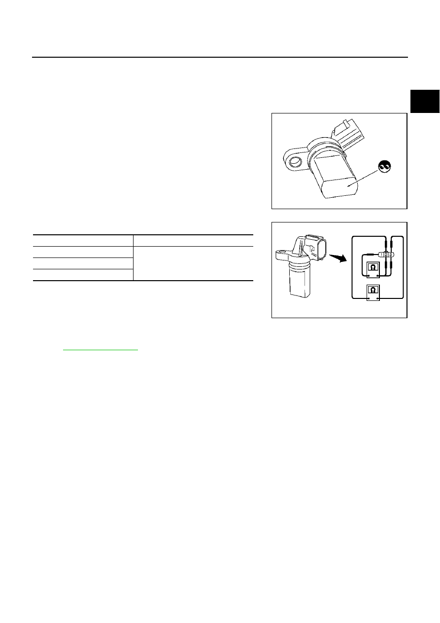
Component Inspection
ABS004GB
CAMSHAFT POSITION SENSOR (PHASE)
1.
Loosen the fixing bolt of the sensor.
2.
Disconnect camshaft position sensor (PHASE) harness connector.
3.
Remove the sensor.
4.
Visually check the sensor for chipping.
5.
Check resistance as shown in the figure.
Removal and Installation
ABS004GC
CAMSHAFT POSITION SENSOR (PHASE)
Refer to
PBIB0563E
Terminal No. (Polarity)
Resistance
Ω
[at 25
°
C (77
°
F)]
1 (+) - 2 (-)
Except 0 or
∞
1 (+) - 3 (-)
2 (+) - 3 (-)
PBIB0564E