Nissan Murano Z50 (2003 year). Manual - part 100
DTC P0327, P0328 KS
EC-319
C
D
E
F
G
H
I
J
K
L
M
A
EC
Revision; 2004 April
2003 Murano
Specification data are reference values and are measured between each terminal and ground.
CAUTION:
Do not use ECM ground terminals when measuring input/output voltage. Doing so may result in dam-
age to the ECM's transistor. Use a ground other than ECM terminals, such as the ground.
Diagnostic Procedure
ABS004FV
1.
CHECK KNOCK SENSOR INPUT SIGNAL CIRCUIT FOR OPEN AND SHORT-I
1.
Turn ignition switch “OFF”.
2.
Disconnect ECM harness connector.
3.
Check resistance between ECM terminal 15 and engine ground. Refer to Wiring Diagram.
NOTE:
It is necessary to use an ohmmeter which can measure more than 10 M
Ω
.
4.
Also check harness for short to ground and short to power.
OK or NG
OK
>> GO TO 4.
NG
>> GO TO 2.
2.
CHECK KNOCK SENSOR INPUT SIGNAL CIRCUIT FOR OPEN AND SHORT-II
1.
Disconnect knock sensor harness connector.
2.
Check harness continuity between ECM terminal 15 and knock
sensor terminal 1.
Refer to Wiring Diagram.
3.
Also check harness for short to ground and short to power.
OK or NG
OK
>> GO TO 4.
NG
>> GO TO 3.
3.
DETECT MALFUNCTIONING PART
Check the following.
●
Harness connectors F9, F241
●
Harness for open or short between ECM and knock sensor
>> Repair open circuit or short to ground or short to power in harness or connectors.
4.
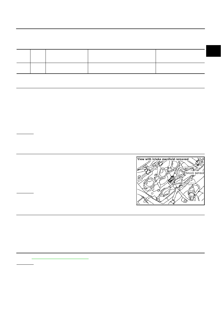
CHECK KNOCK SENSOR
Refer to
EC-320, "Component Inspection"
OK or NG
OK
>> GO TO 5.
NG
>> Replace knock sensor.
TER-
MINAL
NO.
WIRE
COLOR
ITEM
CONDITION
DATA (DC Voltage)
15
W
Knock sensor
[Engine is running]
●
Idle speed
Approximately 2.5V
Resistance: Approximately 532 - 588 k
Ω
[at 20
°
C (68
°
F)]
Continuity should exist.
PBIB1359E