Nissan Murano Z50 (2003 year). Manual - part 66
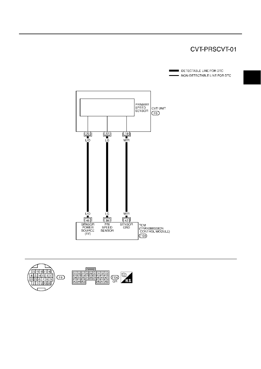
DTC P0715 INPUT SPEED SENSOR CIRCUIT (PRI SPEED SENSOR)
CVT-97
D
E
F
G
H
I
J
K
L
M
A
B
CVT
Revision; 2004 April
2003 Murano
Wiring Diagram - CVT - PRSCVT
ACS0020X
TCWA0156E
|
|
|
DTC P0715 INPUT SPEED SENSOR CIRCUIT (PRI SPEED SENSOR) CVT-97 D E F G H I J K L M A B CVT Revision; 2004 April 2003 Murano Wiring Diagram - CVT - PRSCVT ACS0020X TCWA0156E |