Nissan Murano Z50 (2003 year). Manual - part 65


  Index      Manuals     Nissan Murano Z50 (2003 year) - Service and Repair Manual


Search            copyright infringement  


Content      ..     63      64      65      66     ..


Nissan Murano Z50 (2003 year). Manual - part 65


DTC P0615 START SIGNAL CIRCUIT

CVT-81

D

E

F

G

H

I

J

K

L

M

A

B

CVT

Revision; 2004 April

2003 Murano

TCM terminal and data are reference values. Measured between each terminal and ground.

Diagnostic Procedure

ACS001TQ

1. 

CHECK PNP RELAY (STARTER RELAY) (WITH CONSULT-II)

 With CONSULT-II

1.

Turn ignition switch “ON”. (Do not start engine.)

2.

Select “SELECTION FROM MENU” in “DATA MONITOR” mode
for “TRANSMISSION” with CONSULT-II and check monitor
“STRTR RLY OUT”, “STRTR RLY MON”(PNP relay) ON/OFF.

OK or NG

OK

>> GO TO 4.

NG

>> GO TO 3.

2. 

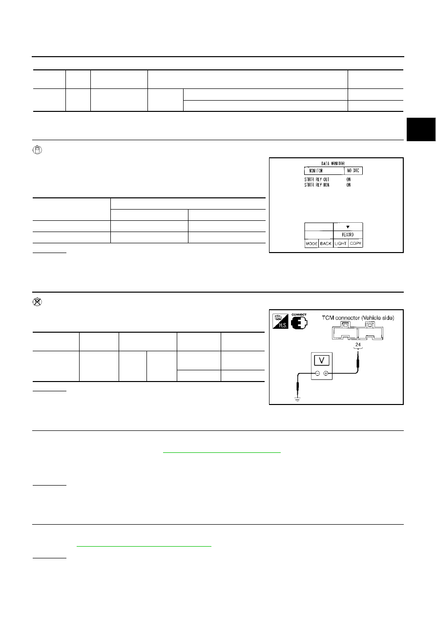
CHECK PNP RELAY (STARTER RELAY) (WITHOUT CONSULT-II)

 Without CONSULT-II

1.

Turn ignition switch “ON”. (Do not start engine.)

2.

Check voltage between the TCM connector and ground.

OK or NG

OK

>> GO TO 4.

NG

>> GO TO 3.

3. 

DETECT MALFUNCTIONING ITEM

Check the following:

PNP relay (starter relay). Refer to 

PG-85, "STANDARDIZED RELAY"

 .

Open or short-circuits in the harness between TCM and the PNP relay

Ground circuit for the PNP relay (starter relay)

OK or NG

OK

>> GO TO 4.

NG

>> Repair or replace damaged parts.

4. 

CHECK DTC

Check again.

Refer to 

CVT-79, "DTC Confirmation Procedure"

 .

OK or NG

OK

>> INSPECTION END

NG

>> GO TO 5.

Terminal 

No.

Wire 

color

Item

Condition

Data (Approx.)

24

G/O

PNP relay
(Starter relay)

IGN ON

Selector lever in “N”, “P” position.

Battery voltage

Selector lever in other position.

0V

Shift position

Item

“STRTR RLY OUT”

“STRTR RLY MON”

N and P

ON

ON

R, D and L

OFF

OFF

SCIA2274E

Item

Connector 

No.

Terminal No.

(Wire color)

Shift position

Voltage 

(Approx.) 

PNP relay
(Starter relay)

F103

24

(G/O)

Ground

N and P

Battery 
voltage

R, D and L

0V

SCIA2022E

CVT-82

DTC P0615 START SIGNAL CIRCUIT

Revision; 2004 April

2003 Murano

5. 

CHECK TCM INSPECTION

1.

Perform TCM input/output signal inspection.

2.

If NG, re-check TCM pin terminals for damage or loose connection with harness connector.

OK or NG

OK

>> INSPECTION END

NG

>> Repair or replace damaged parts.

DTC P0703 STOP LAMP SWITCH CIRCUIT

CVT-83

D

E

F

G

H

I

J

K

L

M

A

B

CVT

Revision; 2004 April

2003 Murano

DTC P0703 STOP LAMP SWITCH CIRCUIT

PFP:25320

Description

ACS002SJ

“ON”, “OFF” status of the stop lamp switch is sent via the CAN communication from the unified meter and the
A/C amp to TCM using the signal.

On Board Diagnosis Logic

ACS002SK

This is not an OBD-II self-diagnostic item. 

Diagnostic trouble code “BRAKE SW/CIRC” with CONSULT-II is detected when the brake switch does not
switch to “ON” and “OFF”.

The brake switch does not switch to “ON”, “OFF”.

Possible Cause

ACS002SL

Harness or connectors
[The stop lamp switch and unified meter and A/C amp circuit is open or shorted.]
[CAN communication line is open or shorted.]

Stop lamp switch

DTC Confirmation Procedure

ACS002SM

NOTE:
If “DTC Confirmation Procedure” has been previously performed, always turn ignition switch “OFF”
and wait at least 10 seconds before performing the next test.
After the repair, touch “ERASE” on “SELF-DIAG RESULTS” and then perform the following procedure to con-
firm the malfunction is eliminated.

 WITH CONSULT-II

1.

Turn ignition switch “ON”. (Do not start engine.)

2.

Select “DATA MONITOR” mode for “TRANSMISSON” with
CONSULT-II.

3.

Start engine.

4.

Start vehicle for at least 3 consecutive seconds.

5.

If DTC is detected, go to 

CVT-83, "Diagnostic Procedure"

 .

Diagnostic Procedure

ACS002IT

1. 

CHECK CAN COMMUNICATION LINE

Perform the self-diagnosis.

Is any malfunction of the “CAN COMM CIRCUIT” indicated?

YES

>> Check CAN communication line. Refer to 

CVT-76, "DTC U1000 CAN COMMUNICATION LINE"

 .

NO

>> GO TO 2.

SCIA2272E

CVT-84

DTC P0703 STOP LAMP SWITCH CIRCUIT

Revision; 2004 April

2003 Murano

2. 

CHECK STOP LAMP SWITCH CIRCUIT

 With CONSULT-II

1.

Turn ignition switch “ON”. (Do not start engine.)

2.

Select “ECU INPUT SIGNALS” in “DATA MONITOR” mode for
“TRANSMISSON” with CONSULT-II.

3.

Read out ON/OFF switching action of the “BRAKE SW”.

OK or NG

OK

>> INSPECTION END

NG

>> GO TO 3.

3. 

CHECK STOP LAMP SWITCH

Check continuity between stop lamp switch harness connector E116 terminals 1 (R/Y) and 2 (R/G).

Check stop lamp switch after adjusting brake pedal — refer to 

BR-6, "BRAKE PEDAL"

 .

OK or NG

OK

>> Check the following. If NG, Repair or Replace Damaged Parts.

Harness for short or open between battery and stop lamp switch.

Harness for short or open between stop lamp switch and unified meter and A/C amp.

NG

>> Repair or Replace the stop lamp switch.

SCIA2275E

SCIA3700E

DTC P0705 PARK/NEUTRAL POSITION SWITCH

CVT-85

D

E

F

G

H

I

J

K

L

M

A

B

CVT

Revision; 2004 April

2003 Murano

DTC P0705 PARK/NEUTRAL POSITION SWITCH

PFP:32006

Description

ACS001TR

The park/neutral position (PNP) switch includes 4 transmission position switches.

TCM judges the selector lever position by the PNP switch signal.

On Board Diagnosis Logic

ACS001TS

This is an OBD-II self-diagnostic item.

Diagnostic trouble code “PNP SW/CIRC” with CONSULT-II or P0705 without CONSULT-II is detected
under the following conditions.

When TCM does not receive the correct voltage signal from the PNP switches 1, 2, 3 and 4 based on the
gear position.

When the signal from monitor terminal of PNP switch 3 is different from PNP switch 3.

Possible Cause

ACS001TT

Harness or connectors
[The park/neutral position (PNP) switches 1, 2, 3, 4 and TCM circuit is open or shorted.]

Park/neutral position (PNP) switches 1, 2, 3, 4 

Park/neutral position (PNP) switch 3 monitor terminal is open or shorted

DTC Confirmation Procedure

ACS001TU

CAUTION:

Always drive vehicle at a safe speed.

NOTE:
If “DTC Confirmation Procedure” has been previously performed, always turn ignition switch “OFF”
and wait at least 10 seconds before performing the next test.
After the repair, touch “ERASE” on “SELF-DIAG RESULTS” and then perform the following procedure to con-
firm the malfunction is eliminated.

 WITH CONSULT-II

1.

Turn ignition switch “ON”. (Do not start engine.)

2.

Select “DATA MONITOR” mode for “ENGINE” with CONSULT-II.

3.

Start engine.

4.

Drive vehicle and maintain the following conditions for at least 2
consecutive seconds.
VHCL SPEED SE: More than 10km/h (6 MPH)
ENG SPEED SIG: More than 450rpm
ACC PEDAL OPEN: More than 1/8

5.

If DTC is detected, go to 

CVT-87, "Diagnostic Procedure"

 .

 WITH GST

Follow the procedure “With CONSULT-II”.

 Shift position

PNP switch 1

PNP switch 2

PNP switch 3

PNP switch 4

PNP switch 3 (monitor)

P

OFF

OFF

OFF

OFF

OFF

R

ON

OFF

OFF

ON

OFF

N

ON

ON

OFF

OFF

OFF

D

ON

ON

ON

ON

ON

L

OFF

ON

ON

OFF

ON

SCIA2272E

CVT-86

DTC P0705 PARK/NEUTRAL POSITION SWITCH

Revision; 2004 April

2003 Murano

Wiring Diagram — CVT — PNP/SW

ACS001TV

TCWA0148E

DTC P0705 PARK/NEUTRAL POSITION SWITCH

CVT-87

D

E

F

G

H

I

J

K

L

M

A

B

CVT

Revision; 2004 April

2003 Murano

TCM terminals and data are reference values. Measured between each terminal and ground.

Diagnostic Procedure

ACS001TW

1. 

CHECK PNP SW CIRCUIT (WITH CONSULT-II)

 With CONSULT-II

1.

Turn ignition switch “ON”. (Do not start engine.)

2.

Select “ECU INPUT SIGNALS” in “DATA MONITOR” mode for
“TRANSMISSON” with CONSULT-II.

3.

Selector lever to “P”, “R”, “N”,“D” and “L” position to check the
value of “INH SW1” “INH SW2” “INH SW3” “INH SW4” and “INH
SW3M”.

OK or NG

OK

>> GO TO 4.

NG

>> GO TO 3.

Terminal No.

Wire color

Item

Condition

Data (Approx.)

27

BR/W

PNP switch 1

IGN ON

Selector lever in “P”, “L” position.

Battery voltage

Selector lever in other position.

0V 

34

P/B

PNP switch 2

Selector lever in “P”, “R” position.

Battery voltage

Selector lever in other position.

0V 

35

P/L

PNP switch 3

Selector lever in “P”, “R”, “N” position.

Battery voltage

Selector lever in other position.

0V 

36

G

PNP switch 4

Selector lever in “P”, “N”, “L” position.

Battery voltage

Selector lever in other position.

0V 

32

GR

PNP switch 3 
(monitor)

Selector lever in “P”, “R”, “N” position.

Battery voltage

Selector lever in other position.

0V 

 Shift 

position

 “INH SW1”

 “INH SW2”

 “INH SW3”

 “INH SW4”

 “INH 

SW3M”

P

OFF

OFF

OFF

OFF

OFF

R

ON

OFF

OFF

ON

OFF

N

ON

ON

OFF

OFF

OFF

D

ON

ON

ON

ON

ON

L

OFF

ON

ON

OFF

ON

SCIA2276E

CVT-88

DTC P0705 PARK/NEUTRAL POSITION SWITCH

Revision; 2004 April

2003 Murano

2. 

CHECK PNP SW CIRCUIT (WITHOUT CONSULT-II)

 Without CONSULT-II

1.

Turn ignition switch “ON”. (Do not start engine.)

2.

Change selector lever to “P“, “R”, “N”, “D” or “L” position to
check voltage between the TCM connector terminals and
ground.

OK or NG

OK >> GO 

TO 

4.

NG

>> GO TO 3. 

3. 

CHECK THE HARNESS BETWEEN TCM AND PNP SWITCH

1.

Turn ignition switch “OFF”.

2.

Disconnect the TCM connector.

3.

Check the continuity between TCM connector terminals (vehicle
side) 27 (BR/W), 34 (P/B), 35 (P/L), 36 (G), 32 (GR) and ground.

4.

If OK, check the harness for short-circuit to ground or the power source. 

OK or NG

OK

>> GO TO 5.

NG

>> GO TO 4.

Shift 

position

Connector No.

F104

Terminal No. (Wire color)

27 (BR/W) - 

Ground

34 (P/B) - 

Ground

35 (P/L) - 

Ground

36 (G) - 

Ground

 32 (GR) - 

Ground

P

Battery 
voltage

Battery 
voltage

Battery 
voltage

Battery 
voltage

 Battery 

voltage

R

0V

Battery 
voltage

Battery 
voltage

0V

 Battery 

voltage

N

0V

0V

Battery 
voltage

Battery 
voltage

 Battery 

voltage

D

0V

0V

0V

0V

0V

L

Battery 
voltage

0V

0V

Battery 
voltage

0V

SCIA2024E

Connector 

No.

Terminal No.

(Wire color)

Condition

Continuity

F104

27 (BR/W) - ground

Select lever in “P”, “L” position.

No

Select lever in other position.

Yes

34 (P/B) - ground

Select lever in “P”, “R” position.

No

Select lever in other position.

Yes

35 (P/L) - ground

Select lever in “P”, “R”, “N” posi-
tion.

No

Select lever in other position.

Yes

36 (G) - ground

Select lever in “P”,“N”,  “L” posi-
tion.

No

Select lever in other position.

Yes

32 (GR) - ground

Select lever in “P”, “R”, “N” posi-
tion.

No

Select lever in other position.

Yes

SCIA2337E

DTC P0705 PARK/NEUTRAL POSITION SWITCH

CVT-89

D

E

F

G

H

I

J

K

L

M

A

B

CVT

Revision; 2004 April

2003 Murano

4. 

DETECT MALFUNCTIONING ITEM

 Check the following items.

Open or short-circuit in the harness between TCM and PNP switch 1, 2, 3, 4.

Open or short-circuit in the harness between TCM and PNP switch 3 monitor.

Open-circuit in ground between TCM and PNP switch (transaxle assembly).

PNP switch. Refer to 

CVT-89, "Component Inspection"

 .

OK or NG

 OK 

>>  GO TO 5.

 NG

>>  Repair or replace damaged parts.

5. 

CHECK DTC

Check again.

Refer to 

CVT-85, "DTC Confirmation Procedure"

 .

OK or NG

OK >> INSPECTION END
NG

>> GO TO 6.

6. 

CHECK TCM INSPECTION

1.

Perform TCM input/output signal inspection.

2.

If NG, re-check TCM pin terminals for damage or loose connection with harness connector.

OK or NG

OK

>> INSPECTION END

NG

>> 1. Repair or replace damaged parts.

2. Replace the transaxle assembly. Refer to 

CVT-197, "Removal and Installation"

 .

Component Inspection

ACS001TX

PNP SWITCH

1.

Change selector lever to various positions to check the continu-
ity between terminals on the PNP switch and ground.

2.

If NG, check the continuity with the control linkage disconnected. (Refer to Step 1 above.)

3.

If OK with the control linkage disconnected, adjust the control linkage. Refer to 

CVT-183, "Adjustment of

CVT Position"

 .

4.

If NG even when the control linkage is disconnected, replace the transaxle assembly. Refer to 

CVT-197,

"Removal and Installation"

 .

PNP SW

Shift position

Connector No.

Terminal No.

Continuity

SW 1

R, N, D

F6

4 - Ground

Yes

other position.

No

SW 2

N, D, L

5 - Ground

Yes

other position.

No

SW 3

D, L

14 - Ground

Yes

other position.

No

SW 4

R, D

15 - Ground

Yes

other position.

No

SW 3 
Monitor

D, L

 18 - Ground

Yes

other position.

No

SCIA2025E

CVT-90

DTC P0710 CVT FLUID TEMPERATURE SENSOR CIRCUIT

Revision; 2004 April

2003 Murano

DTC P0710 CVT FLUID TEMPERATURE SENSOR CIRCUIT

PFP:31020

Description

ACS002SN

The CVT fluid temperature sensor detects the CVT fluid temperature and sends a signal to the TCM.

CONSULT-II Reference Value

ACS002SO

Remarks: Specification data are reference values.

On Board Diagnosis Logic

ACS002SP

This is an OBD-II self-diagnostic item.

Diagnostic trouble code “ATF TEMP SEN/CIRC” with CONSULT-II or P0710 without CONSULT-II is
detected when TCM receives an excessively low or high voltage from the sensor.

Possible Cause

ACS002SQ

Harness or connectors
(The sensor circuit is open or shorted.)

CVT fluid temperature sensors

DTC Confirmation Procedure

ACS002SR

CAUTION:

Always drive vehicle at a safe speed.

NOTE:
If “DTC Confirmation Procedure” has been previously performed, always turn ignition switch “OFF”
and wait at least 10 seconds before performing the next test.
After the repair, touch “ERASE” on “SELF-DIAG RESULTS” and then perform the following procedure to con-
firm the malfunction is eliminated.

 WITH CONSULT-II

1.

Turn ignition switch “ON”. (Do not start engine.)

2.

Select “DATA MONITOR” mode for “ENGINE” with CONSULT-II.

3.

Start engine and maintain the following conditions for at least 10
minutes (Total). (It is not necessary to maintain continuously.)
VHCL SPEED SE: 10 km/h (6 MPH) or more
ENG SPEED: 450rpm more than
ACC PEDAL OPEN: More than 1/8
Selector lever: “D” position

4.

If DTC is detected, go to 

CVT-92, "Diagnostic Procedure"

 .

 WITH GST

Follow the procedure “With CONSULT-II”.

 Monitor item

 Condition

 Specification (Approximately)

 CVT fluid temperature sensor

 Cold [20

°

C (68

°

F)]

 2.0V

 Hot [80

°

C (176

°

F)]

 1.0V

SCIA2272E

DTC P0710 CVT FLUID TEMPERATURE SENSOR CIRCUIT

CVT-91

D

E

F

G

H

I

J

K

L

M

A

B

CVT

Revision; 2004 April

2003 Murano

Wiring Diagram - CVT - FTS

ACS0020Q

TCWA0149E

CVT-92

DTC P0710 CVT FLUID TEMPERATURE SENSOR CIRCUIT

Revision; 2004 April

2003 Murano

TCM terminals and data are reference values. Measured between each terminal and ground.

Diagnostic Procedure

ACS002SS

1. 

CHECK FLUID TEMPERATURE SENSOR SIGNAL (WITH CONSULT-II)

 With CONSULT-II

1.

Start engine.

2.

Select “ECU INPUT SIGNALS” in “DATA MONITOR” mode for
“TRASMISSION” with CONSULT-II.

3.

Read out the value of “ATF TEMP SEN”.

OK or NG

OK >> GO 

TO 

6.

NG

>> GO TO 3.

2. 

CHECK FLUID TEMPERATURE SENSOR SIGNAL (WITHOUT CONSULT-II)

 Without CONSULT-II

1.

Start engine.

2.

Check voltage between TCM connector and ground while warming up CVT. Refer to 

CVT-91, "Wiring Dia-

gram - CVT - FTS"

 .

3.

Turn ignition switch “OFF”.

4.

Disconnect the TCM connector.

5.

Check if there is continuity between the connector terminal and
ground.

OK or NG

OK >> GO 

TO 

6.

NG

>> GO TO 3.

Terminal 

No.

Wire color

Item

Condition

Judgement standard

(Approx.)

42

W/R

Sensor ground

47

V

CVT fluid tempera-
ture sensor

When CVT fluid temperature is 20

°

C (68

°

F).

2.0V

When CVT fluid temperature is 80

°

C (176

°

F).

1.0V

Item name

Condition 

°

C (

°

F)

Display value (Approx.) V

CVT fluid temperature 
sensor

20 (68)

2.0

80 (176)

1.0

SCIA2277E

Name

Connector 

No.

Terminal No.

Temperature 

°

C (

°

F)

Voltage (V) 

(Approx.)

Fluid tempera-
ture sensor 1

F104

47 (V) - 42 (W/R) 

(ground)

20 (68)

2.0

80 (176)

1.0

SCIA2027E

DTC P0710 CVT FLUID TEMPERATURE SENSOR CIRCUIT

CVT-93

D

E

F

G

H

I

J

K

L

M

A

B

CVT

Revision; 2004 April

2003 Murano

3. 

CHECK FLUID TEMPERATURE SENSOR CIRCUIT

1.

Turn ignition switch “OFF”.

2.

Disconnect the TCM connector.

3.

Check resistance between terminals 47 and 42.

4.

Disconnect the TCM connector.

5.

Check if there is continuity between the connector terminal and
ground.

OK or NG

 OK 

>> GO TO 6.

 NG

>> GO TO 4.

4. 

 CHECK FLUID TEMPERATURE SENSOR

1.

Turn ignition switch “OFF”.

2.

Disconnect CVT unit harness connector.

3.

Check resistance between terminals 17 and 19.

4.

Reinstall any part removed.

OK or NG

OK

>> GO TO 5.

NG

>> Replace the transaxle assembly. Refer to 

CVT-197,

"Removal and Installation"

 .

5. 

 CHECK THE HARNESS BETWEEN TCM AND CVT FLUID TEMPERATURE SENSOR

1.

Turn ignition switch “OFF”.

2.

Disconnect the TCM connector and CVT unit harness connector.

3.

Check continuity between TCM connector and CVT unit harness
connector.

4.

If OK, check harness for short to ground and short power.

5.

Reinstall any part removed.

OK or NG

 OK

>>  GO TO 6.

 NG

>>  Repair or replace damaged parts.

Name

Connector 

No.

Terminal No. 

(Wire color)

Temperature 

°

C (

°

F)

Resistance 

(K

) (Approx.)

CVT fluid 
tempera-
ture sensor

F104

 47 (V) - 42 (W/

R) (ground)

20 (68)

2.5

80 (176)

0.3

SCIA2338E

Name

Connector

 No.

Terminal No.

Temperature 

°

C (

°

F)

Resistance 

(K

) (Approx.)

CVT fluid 
tempera-
ture sensor

F6

17 - 19

20 (68)

2.5

80 (176)

0.3

SCIA2026E

 Item

 Connector No.

 Terminal No. 

(Wire color)

 Continuity

 TCM

 F104

 42 (W/R)

 Yes

 CVT unit harness connector

 F6

 19 (W/R)

 Item

 Connector No.

 Terminal No. 

(Wire color)

 Continuity

 TCM

 F104

 47 (V)

 Yes

 CVT unit harness connector

 F6

 17 (V)

SCIA2339E

CVT-94

DTC P0710 CVT FLUID TEMPERATURE SENSOR CIRCUIT

Revision; 2004 April

2003 Murano

6. 

CHECK DTC

Perform “DTC Confirmation Procedure”. Refer to 

CVT-90, "DTC Confirmation Procedure"

 .

OK or NG

OK

>> INSPECTION END

NG

>>  GO TO 7.

7. 

PERFORM TCM INSPECTION

1.

Perform TCM input/output signal inspection.

2.

If NG, re-check TCM pin terminals for damage or loose connection with harness connector.

OK or NG

OK

>> INSPECTION END

NG

>> Repair or replace damaged parts.

Component Inspection

ACS003KY

CVT FLUID TEMPERATURE SENSOR

1.

Turn ignition switch “OFF”.

2.

Disconnect CVT unit harness connector.

3.

Check resistance between terminals 17 and 19.

4.

If NG, replace transaxle assembly. Refer to 

CVT-197, "Removal

and Installation"

 .

 Name

 Connector 

No.

 Terminal No. 

(Wire color)

 Temperature 

°

C (

°

F)

 Resistance 

(K

) (Approx.)

 CVT fluid 
tempera-
ture sensor

 F6

 17 (V) - 19 (W/R)

 20 (68)

 2.5

 80 (176)

 0.3

SCIA2026E

DTC P0715 INPUT SPEED SENSOR CIRCUIT (PRI SPEED SENSOR)

CVT-95

D

E

F

G

H

I

J

K

L

M

A

B

CVT

Revision; 2004 April

2003 Murano

DTC P0715 INPUT SPEED SENSOR CIRCUIT (PRI SPEED SENSOR)

PFP:31935

Description

ACS002ST

The input speed sensor (primary speed sensor) detects the primary pulley revolution speed and sends a sig-
nal to the TCM.
NOTE:
CONSULT-II screen terms are shown differently depending on the version of CONSULT-II card.

CONSULT-II Reference Value

ACS002SU

Remarks: Specification data are reference values.

On Board Diagnosis Logic

ACS002SV

This is an OBD-II self-diagnostic item.

Diagnostic trouble code “IN PY SPD SEN/CIRC” with CONSULT-II or P0715 without CONSULT-II is
detected when TCM does not receive the proper signal from the sensor.

Possible Cause

ACS002SW

Harness or connectors
(The sensor circuit is open or shorted.)

Input speed sensor (primary speed sensor)

DTC Confirmation Procedure

ACS002SX

CAUTION:

Always drive vehicle at a safe speed.

Be careful not to rev engine into the red zone on the tachometer.

NOTE:
If “DTC Confirmation Procedure” has been previously performed, always turn ignition switch “OFF”
and wait at least 5 seconds before performing the next test.
After the repair, touch “ERASE” on “SELF-DIAG RESULTS” and then perform the following procedure to con-
firm the malfunction is eliminated.

 WITH CONSULT-II

1.

Turn ignition switch “ON” and select “DATA MONITOR” mode for
“ENGINE” with CONSULT-II.

2.

Start engine and maintain the following conditions for at least 5
consecutive seconds.
VHCL SPEED SE: 10 km/h (6 MPH) or more
ACC PEDAL OPEN: More than 1/8
Selector lever: D position
ENG SPEED: 450 rpm or more
Driving location: Driving the vehicle uphill (increased
engine load) will help maintain the driving conditions
required for this test.

Monitor item

Condition

Specification (Approximately)

 ENG SPEED SIG

Engine running

Closely matches the tachometer reading.

PRI SPEED SEN

During driving (lock-up ON)

Approximately matches the engine speed.

SCIA2272E

CVT-96

DTC P0715 INPUT SPEED SENSOR CIRCUIT (PRI SPEED SENSOR)

Revision; 2004 April

2003 Murano

If the check result is NG, go to “Diagnostic Procedure”, 

CVT-98

 .

 WITH GST

Follow the procedure “With CONSULT-II”.

SCIA5492E


Content      ..     63      64      65      66     ..